Getting Started
R&S
®
FSW
57User Manual 1173.9411.02 ─ 43
2
1
13 14
3 6
12
8
16
4
10
15 17
9
11
1918
5
7
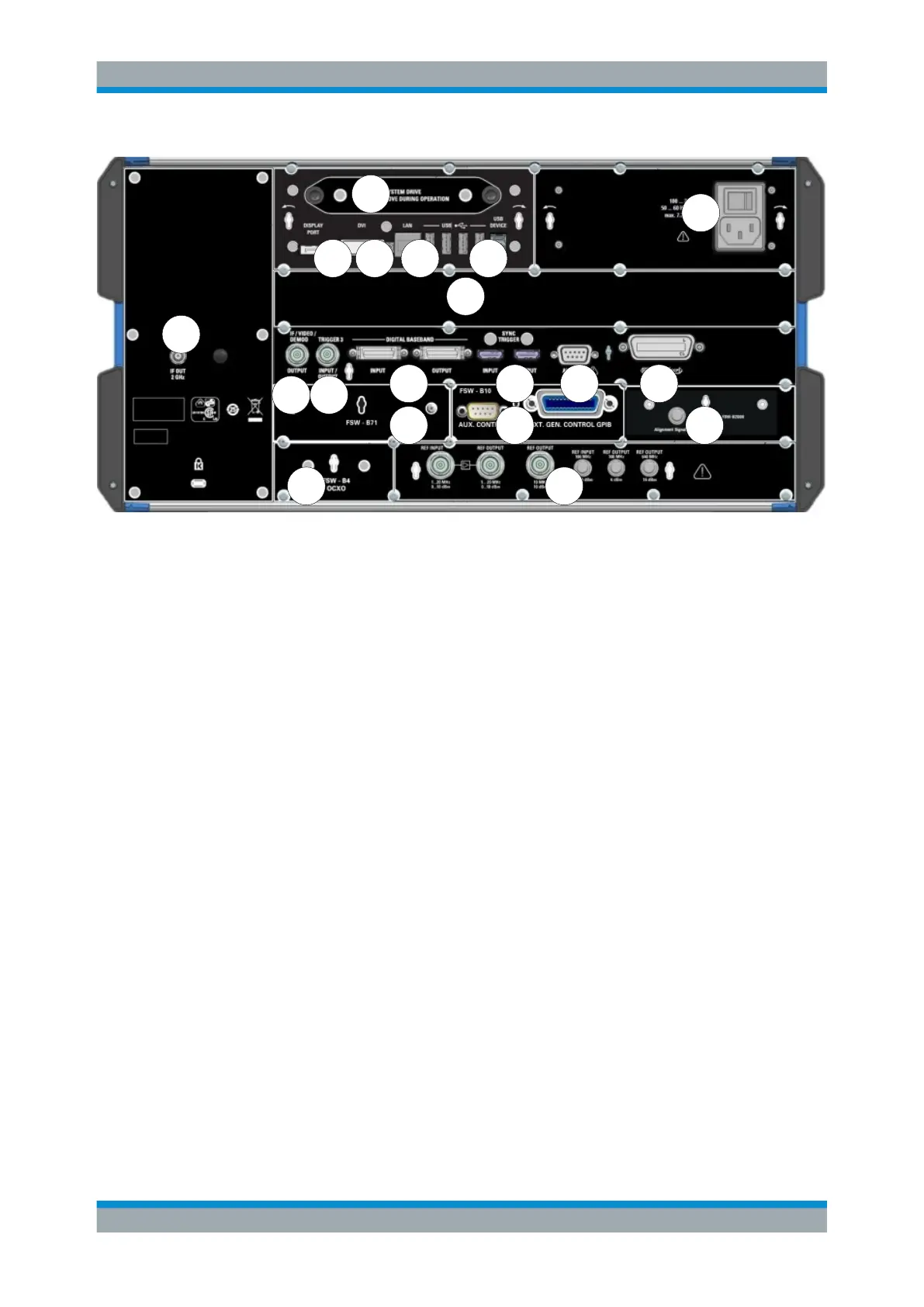
Figure 5-3: Rear panel view
1 = Removable system hard drive
2 = AC Power Supply Connection and Main Power Switch
3 = DISPLAY PORT for external display
4 = DVI connector for external display
5 = LAN connector
6 = USB (DEVICE) connectors
7 = Bandwidth Extension 160 MHz/ 320 MHz/ 512 MHz with IF WIDE OUTPUT connector (option -B160/-
B320-B512)
8 = IF OUT 2 GHz connector
9 = IF/VIDEO/DEMOD connector
10 = TRIGGER 3 INPUT/OUTPUT connector
11 = DIGITAL BASEBAND INPUT/OUTPUT connectors (option B17)
12 = SYNC TRIGGER OUTPUT/INPUT
13 = AUX PORT
14 = GPIB interface
15 = Analog baseband interface (option B71)
16 = External generator control (option B10)
17 = Alignment Signal Source (option B2000)
18 = OCXO external reference (option B4)
19 = REF INPUT/OUTPUT connectors
5.2.2.1 Removable System Hard Drive
The removable system hard drive contains all measurement data from the R&S FSW,
allowing you to store the data securely in an external location.
5.2.2.2 AC Power Supply Connection and Main Power Switch
An AC power supply connector and main power switch are located in a unit on the rear
panel of the instrument.
Instrument Tour

 Loading...


