Section 07 ENGINE MANAGEMENT (DI)
Subsection 02 (COMPONENT INSPECTION AND ADJUSTMENT)
4
F12R0XA
5 8 6 2 3
71
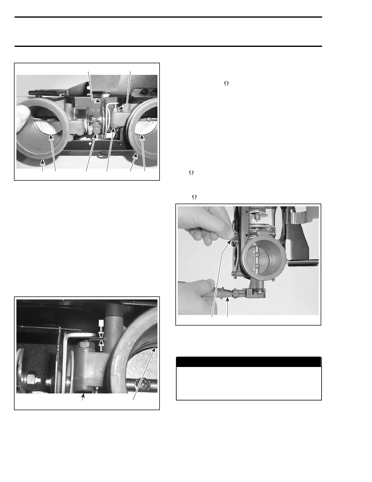
1. Throttle cable attachment
2. Master throttle body
3. Master throttle plate
4. Slave throttle body
5. Slave throttle plate
6. Idle set screw
7. Lock nut
8. Synchronizing screw with its tamper proof cap
NOTE: In the following illustrations, the lower link
plate has been removed for clarity purposes only.
It does not have to be removed to perform the
adjustment.
Loosen lock nut of idle set screw.
Unscrew idle set screw so that master throttle
plate completely closes in the throttle body. En-
sure screw end clears the lever stopper.
2
F12R0YA
1
3
1. Unscrew until master throttle plate is fully closed in throttle body
2. Unscrew here
3. Gap here
Remove synchronizing screw and spring between
levers.
NOTE: The 175
resistance mentioned below is
used to open the throttle plates the same amount
on each throttle body to obtain the proper synchro-
nization. It is the equivalent of using a drill bit in
the throttle bore to open throttle plate on carbure-
tors.
Master TPS
Snap throttle plate a few times to ensure it is com-
pletely closed.
Using an ohmmeter, measure resistance between
terminals 2 and 3. Note the resistance value. Add
175
to that value.
Turn idle set screw clockwise until ohmme-
ter reading reaches the computed value above
±20
.
F12R1BA
12
1. Measure resistance between terminals 2 and 3
2. Turn screw clockwise to
increase resistance
Tighten lock nut.
WARNING
Do not apply any threadlocker on the screw
threads. The threadlocker may leak off the
screw and onto the throttle mechanism and
cause the throttle to stick.
Recheck reading and readjust as necessary.
340 smr2004-Complete Line Up

 Loading...


