Section 07 ENGINE MANAGEMENT (DI)
Subsection 02 (COMPONENT INSPECTION AND ADJUSTMENT)
Adjustment
In this operation, the ignition timing light and
B.U.D.S. are used to synchronize the MPEM TDC
reference with the engine crankshaft. This timing
adjustment will affect the timing of ignition as
well as direct injector timings. The aim of the
adjustment is to align the mark on the flywheel
with the pointer at idle using the timing light and
B.U.D.S. When this is achieved, then the MPEM
TDC reference is synchronized with the engine
crankshaft.
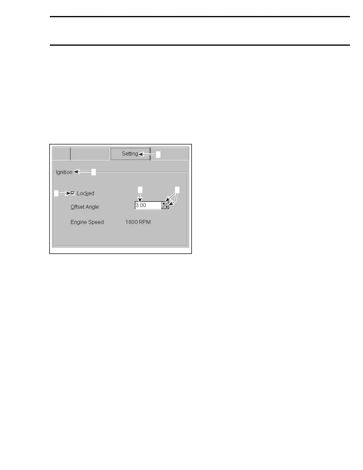
F17H08A
1
2
3
4 5
1. “Setting” tab
2. Ignition section
3. “Locked” box
4. Current angle in MPEM
5. Arrows to change the angle
– Choose the Setting tab and look under Ignition.
– Check the Locked box to “freeze” the timing at
the correct value.
– The VCK displays the number that is stored in
the MPEM.
– Nowclicktheupordownarrowtochangethe
number of the current angle so that the set-
ting marks align when checking with the timing
light. Each step makes an adjustment of 1/4 de-
gree.
NOTE: Each time the setting is changed on the
screen, the new value is also changed in the
MPEM, so there may be a slow response, do not
make changes too quickly.
– When marks align, uncheck the Locked box to
finish.
NOTE: This will write the new value immediately
in the MPEM. There is no need to press the “Write
data” button to transfer the data to the MPEM un-
less other changes were made. However, we rec-
ommend to reset the service hours when you per-
form a service action such as the ignition timing
setting.
NOTE: The MPEM features a permanent (non-
volatile) memory and keeps the ignition timing set-
ting programmed even when the watercraft bat-
tery is disconnected.
Engine Start/Stop Switch Verification
A quick operation test can be done using the ve-
hicle communication kit (VCK) with the B.U.D.S.
software, using the MONITORING section. Press
the start button and look at the Start button LED.
It should turn on, indicating the starting system
isworkingontheinputside(startbutton,MPEM
and wiring). You know now the problem is on the
output side (MPEM output signal to starting sole-
noid, wiring harness going to the solenoid, starter
motor. Refer to STARTING SYSTEM for testing
procedures). Otherwise, check the input side as
follows.
Disconnect the YELLOW/RED wire of the start/
stop switch. Using an ohmmeter, connect test
probes to YELLOW/RED wire and to ground.
Measure resistance, it must be an open circuit
(switch is normally open). Depress and hold
switch, the ohmmeter should read close to
0 ohm. Otherwise, replace switch.
If the switch tests good, check continuity of cir-
cuits 2-8 and 2-12 using a multimeter.
If wiring harness tests good, it could be the
MPEM. Try a new MPEM referring to MPEM
REPLACEMENT procedures elsewhere in this
section.
Safety Lanyard Switch Verification
If 2 short beeps are not heard when installing
the safety lanyard, refer to DIAGNOSTIC PROCE-
DURES.
The following continuity tests can also be per-
formed using an ohmmeter:
Disconnect switch wires.
smr2004-Complete Line Up 371

 Loading...


