Section12ELECTRICALSYSTEM
Subsection 01 (IGNITION SYSTEM)
90
80
70
60
50
40
30
20
10
0
1
F01H4LA
TYPICAL
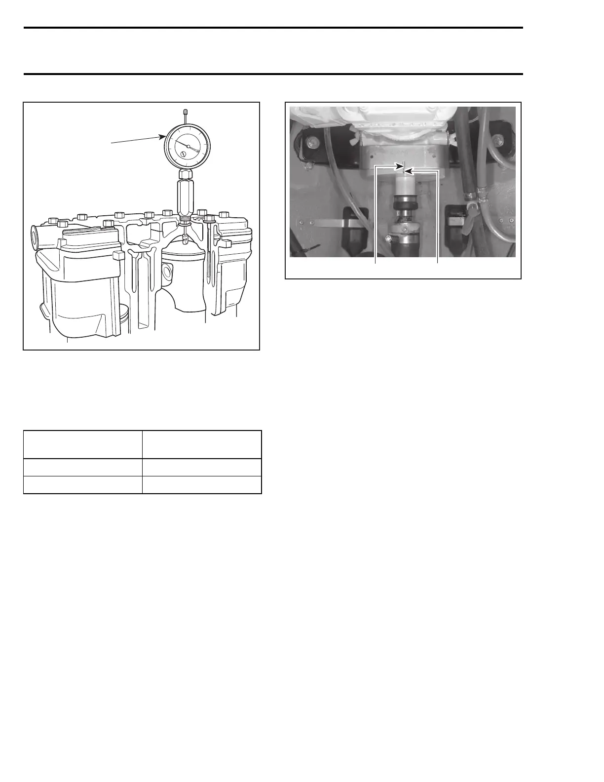
1. Adjust gauge dial at zero
– From this point, rotate flywheel clockwise to
reach proper specification according to engine.
Refer to the following chart.
ENGINE IGNITION TIMING
(BTDC)
717
2.59 mm (.102 in)
787 RFI 1.02 mm (.040 in)
– Scribe a thin mark on PTO flywheel in the mid-
dle of tool slot (717 engines) or aligned with tim-
ing mark pointer tool (787 RFI engines).
F01H5SB
1
2
TYPICAL
1. Tool slot
2. Flywheel mark
NOTE: This mark becomes the reference when
using the stroboscopic timing light.
CAUTION: The static test cannot be used as a
timing procedure, therefore, always check the
timing with a stroboscopic timing light.
– Remove TDC gauge.
– Reinstall spark plug and connect wire.
Dynamic Test
To check ignition timing, use a timing light (avail-
able at local facilities).
NOTE: Ensure to use a timing light capable to
work with 2-stroke engines.
717 Engines
NOTE: To perform this procedure, make sure to
useastroboscopictiminglightratedupto6000
RPM. Otherwise, an inaccurate reading will be ob-
tained.
The ignition components are affected by tempera-
ture variation, therefore, timing must be checked
when engine is cold, after idling for a MAXIMUM
of 20 seconds.
– Connect an induction-type tachometer
(P/N 529 014 500) to spark plug wire.
546 smr2004-Complete Line Up

 Loading...


