Section13PROPULSION
Subsection 02 (DRIVE SYSTEM)
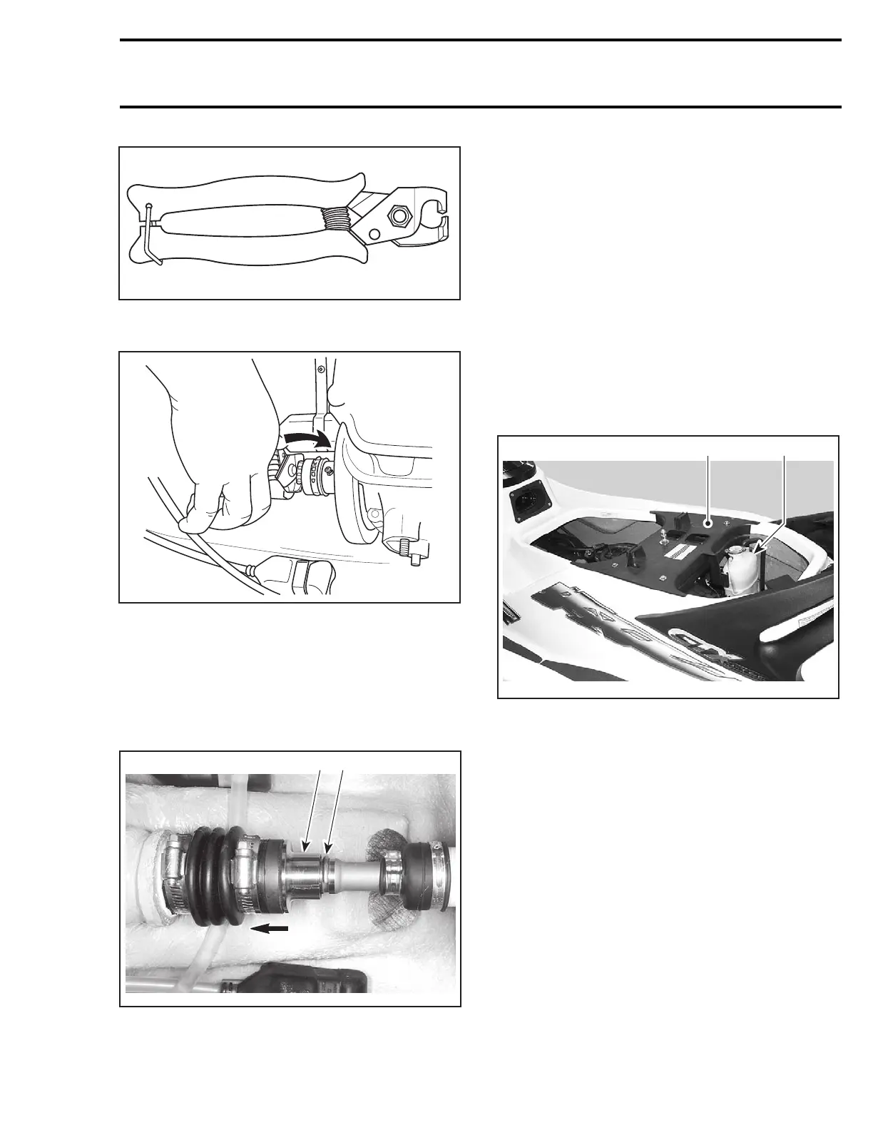
F01B1TA
– To open clamp, place flat side of plier on clamp
embossment, squeeze and twist plier.
F02J0PA
Circlip and Floating Ring
GTI Series and XP DI Models
NOTE: On XP DI models, open rear access cover
to reach boot no. 10 and floating ring no. 6.
Hold floating ring no. 6 and compress boot no. 10;
then, pull out circlip no. 5 from drive shaft groove.
F06I06A
1 2
TYPICAL
1. Push floating ring
2. Remove circlip
4-TEC Models
NOTE: When drive shaft will be removed, some
oil will flow out. To prevent it, start engine, run at
4000 RPM for 10 seconds and stop engine at this
RPM. This will move oil out of PTO housing into
oil tank. If engine cannot be started, refer to the
procedure in PTO HOUSING/MAGNETO section
and look for PTO HOUSING REMOVAL.
Remove seat.
RXP 4-TEC Models
Remove engine cover.
GTX 4-TEC Models
Detach coolant expansion reservoir from vent
tube support then move away.
2
F18L1GB
1
1. Detach expansion reservoir
2. Remove vent tube support
Detach vent tube.
Remove vent tube support.
4-TEC Supercharged Models
Remove supercharger. Refer to INTAKE SYSTEM
in ENGINE SECTION.
All 4-TEC Models
CAUTION: Strictly follow this procedure other-
wise damage to component might occur. Lift
splash guard to expose PTO seal assembly. In-
stall PTO seal support tool (P/N 529 035 842) on
bottom of PTO seal assembly as shown.
smr2004-Complete Line Up 657

 Loading...


