Section 13 PROPULSION
Subsection 02 (DRIVE SYSTEM)
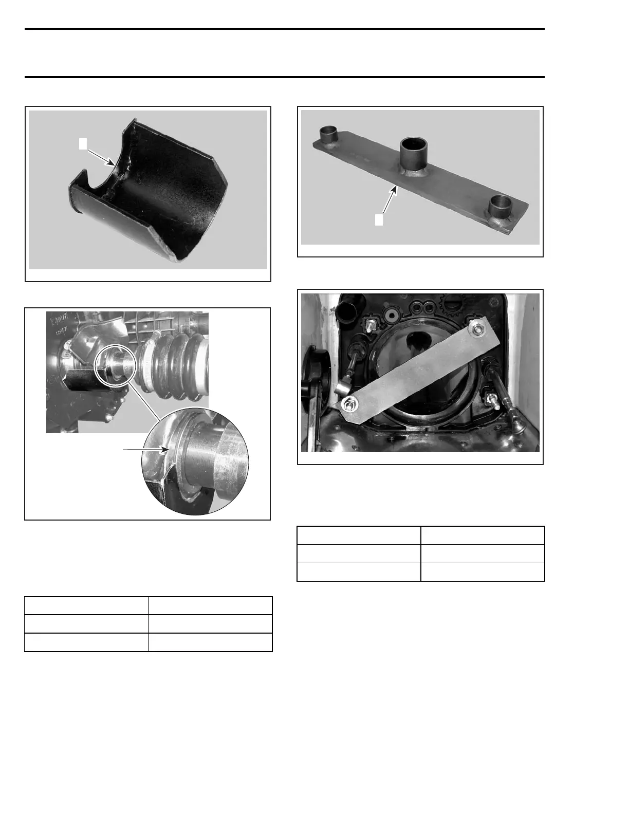
F18B01A
1
1. PTO seal support tool
F18I04A
1
1. Insert in groove of PTO seal assembly
Remove jet pump. Refer to JET PUMP section.
Install drive shaft holder on pump support as
shown.
MODEL TOOL P/N
GTX 4-TEC
529 035 871
RXP 4-TEC
529 035 986
NOTE: This is necessary so the drive shaft cannot
move rearwards when using the drive shaft/float-
ing ring tool.
F18B02A
1
TYPICAL
1. Drive shaft holder
F18B03A
Disconnect EGTS sensor to make room.
For the following operations, use the drive
shaft/floating ring tool .
MODEL TOOL P/N
GTX 4-TEC
529 035 841
RXP 4-TEC
529 035 987
NOTE: Note that there is a large opening and
a small opening on the tool. Depending on the
step involved in the procedure, it is sometimes
required to reverse its installation position.
658 smr2004-Complete Line Up

 Loading...


