Multi Pro 5800 Page 6 − 75 Electrical System
Fuel Level Sender (Diesel Engines Only)
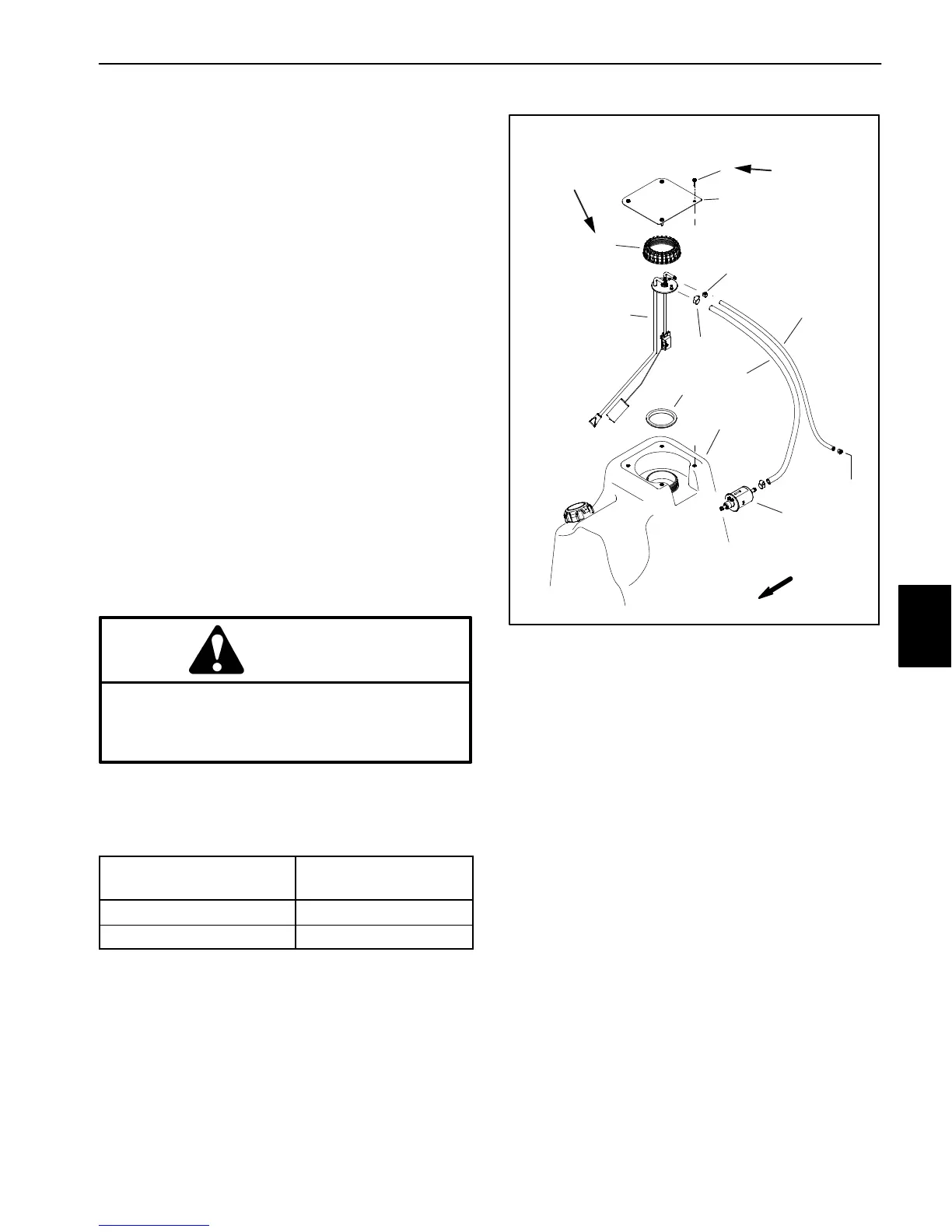
On machines with a diesel engine, the fuel sender is at-
tached to the top of the fuel tank (Fig. 112). The resist-
ance of the fuel sender decreases as the fuel level in the
fuel tank decreases. The fuel sender is connected to a
fuel gauge mounted to the instrument panel.
Testing
1. Park machine on a level surface, stop engine and en-
gage parking brake.
2. Remove fuel tank cover and disconnect machine
wire harness connector from fuel sender.
3. To test the circuit wiring and instrument panel fuel
gauge, turn ignition switch to RUN/PREHEAT. The in-
strument panel fuel gauge should indicate full. Turn igni-
tion switch OFF and proceed with fuel sender testing if
circuit wiring and instrument panel fuel gauge are func-
tioning correctly.
4. Label fuel hoses for assembly purposes then loosen
hose clamps and carefully disconnect fuel supply and
return hoses from fittings on the top of the fuel sender.
5. Remove cap and carefully lift fuel sender and gasket
from fuel tank. Clean all fuel from the sender.
CAUTION
Make sure fuel sender is completely dry (no fuel
on it) before testing. Perform test away from the
fuel tank to prevent an explosion or fire from
sparks.
6. Using a multimeter, check resistance across the fuel
sender connector terminals with the float in the full and
empty positions (Fig. 111).
FLOAT ARM
POSITION
RESISTANCE
FULL (UP) 89 to 95 ohms
EMPTY (DOWN) 5 to 8 ohms
Figure 111
7. Replace fuel sender as necessary.
8. When testing is complete, clean the fuel pick−up
screen and carefully fit gasket and fuel sender into fuel
tank. Make sure fuel sender float arm is facing forward
as shown (Fig. 112).
1. Flange head screw (4)
2. Tank cover
3. Cap
4. Fuel level sender
5. Hose clamp (2)
6. Fuel hose − return
7. Hose clamp (2)
8. Fuel hose − supply
9. Gasket
10. Fuel tank
11. Fuel pump
Figure 112
FRONT
9
4
3
2
1
7
5
6
8
11
FROM
FUEL
RAIL
13 to 65 in−lb
(1 to 7 N−m)
10 to 12 in−lb
(1 N−m)
10
9. Secure fuel sender to tank with cap and tighten cap
from 175 to 200 in−lb (20 to 22 N−m). To prevent dam-
age to fuel sender during assembly, make sure that fuel
sender does not turn as sender cap is tightened.
10.Secure wire harness connector to fuel sender.
11.Connect fuel supply and return hoses to fittings on
the top of the fuel sender and secure hoses with hose
clamps.
12.Bleed fuel system (see Operator’s Manual).
13.Make sure that no fuel leaks exist and install the fuel
tank cover before returning machine to service. Tighten
fuel tank cover screws from 11 to 12 in−lb (1 N−m).
Electrical
System

 Loading...


