Multi Pro 5800Page 8 − 26GeoLink Spray System
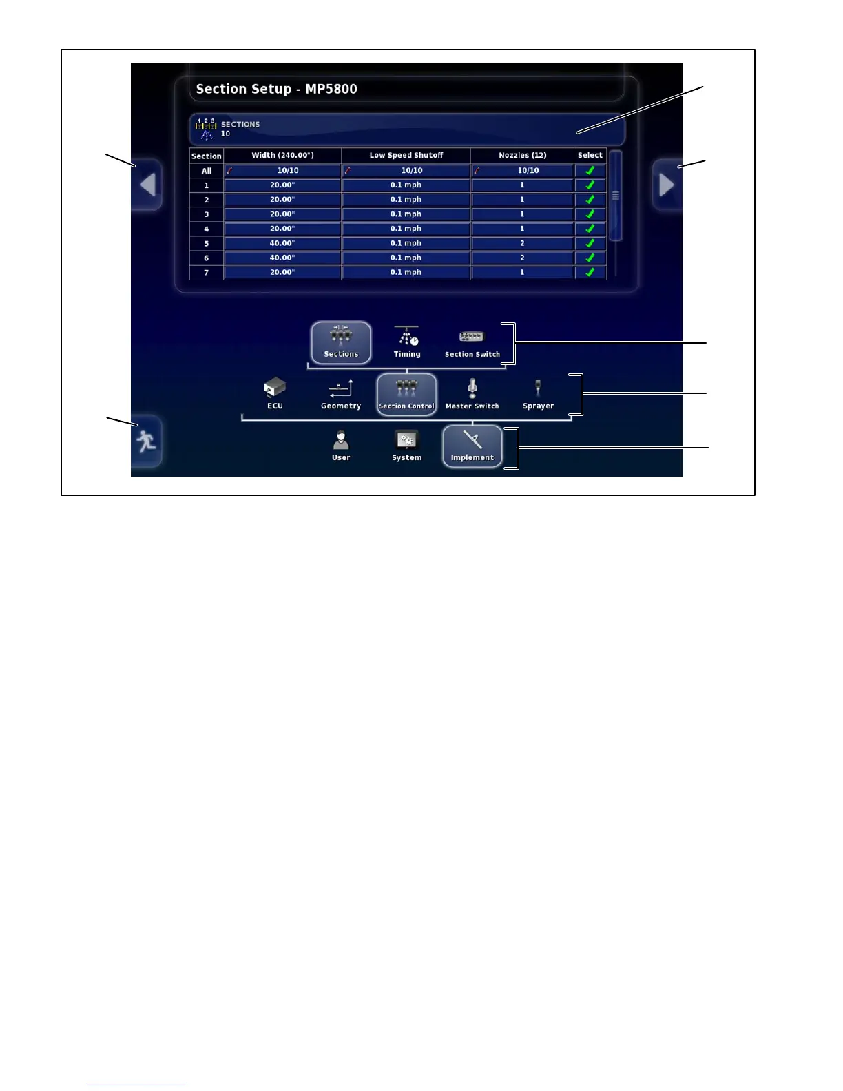
1. Return home icon
2. Previous setup sub−menu
3. Next setup sub−menu
4. First level sub−menus
5. Second level sub−menus
6. Third level sub−menus (when used)
7. Sub−menu details/selections
Figure 27
1
2
3
4
5
6
7
The following outline is intended to illustrate the various
setup screen sub−menu locations and provide a brief
description of their usage. The setup screen with the Im-
plement>Section Control>Sections sub−menu selected
is shown (Fig. 27).
IMPLEMENT
ECU (ASC−10)
ECU setup (name and firmware version)
ECU simulation mode
Geometry (enter precise sprayer dimensions so the
guidance system can function accurately)
Boom location in relation to the sprayer
Boom width
Spray nozzle locations
Section Control (a section is defined by what a sec-
tion valve/nozzle valve controls)
Section width
Low speed shutoff
Number of nozzles per section (center sections
operate two nozzles each)
Section timing (ON and OFF)
Section switching
Master Switch Setup
Virtual (on X25 or X30 console)
External (on operator control console)
Sprayer (setup)
Tank
Flow
Pressure
Pressure Control
Control Valve
Pump Speed
Speed Source
Audio

 Loading...


