Multi Pro 5800Page 8 − 54GeoLink Spray System
Automatic Section Controller (ASC−10)
The controller opens and closes the various nozzle
valves, turning ON the flow of product to a nozzle as it
enters an area that has not been sprayed, and turning
OFF a nozzle as it exits an area that has already been
sprayed. The controller is also responsible for varying
the spray pump speed/system pressure and therefore
the application rate.
The controller is attached to the nozzle valve mount at
the rear of the machine (Fig. 62). Unswitched power is
provided to the controller as long as the battery cables
are connected to the battery. A 50 amp fuse provides cir-
cuit protection for the unswitched power to the con-
troller.
Three diagnostic LEDs are provided on the ASC−10 lo-
cated near the CAN−bus connecter:
STATUS: switched and unswitched power supply
status (flashing blue = OK)
RS232: not used
CAN: CAN−bus network status (flashing green =
OK)
The ASC−10 monitors the states of the following com-
ponents: boom section switches, flow meter and pres-
sure transducer.
The ASC−10 controls electrical output to the following
components: spray pump control solenoid and nozzle
valves.
The AGI−4 antenna, X25 or X30 control console and
ASC−10 auto section controller communicate with each
other on a CAN−bus network. The GeoLink Can−bus
network is separate from the sprayer traction unit CAN−
bus.
The connection terminal functions for the ASC−10 are
shown (Fig. 64). A forty (40) pin wire harness connector
and a four (4) pin wire harness connector attach to the
controller. The four (4) pin connector supports the
GeoLink CAN−bus network. The layout of the wire
harness connectors is shown (Fig. 63). See the
electrical schematics and wire harness drawings and
diagrams in Chapter 11 − Foldout Drawings in this
manual for additional information.
The GeoLink Spray System electrical schematic and
wire harness drawings in Chapter 11 − Foldout Draw-
ings can be used to identify possible circuit problems
between the controller and the input/output devices
(e.g. switches and valves).
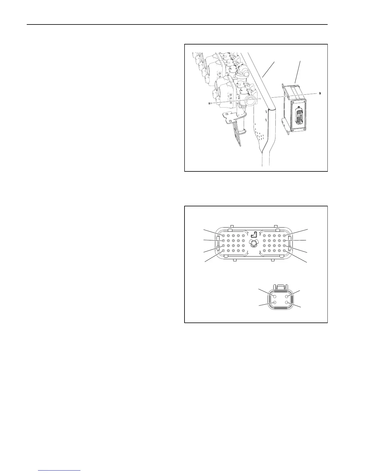
1. Nozzle valve mount 2. Automatic section
controller (ASC−10)
Figure 62
1
2
Figure 63
WIRE HARNESS CONNECTORS FOR ASC−10
10
20
30
40
1
11
21
31
1
2
3
4
P40
P59
12 VDC UNSWITCHED − PINS 30, 39, 40
GROUND − PINS 9, 19, 29
Because of the solid state circuitry built into the ASC−10,
there is no method to test the controller directly. The con-
troller may be damaged if an attempt is made to test it
with an electrical test device (e.g. digital multimeter or
test light).
NOTE: The ASC−10, the X25 or X30 control console,
the GPS antenna assembly (including the modem and
the IMU for machines with RTK correction) are pro-
grammed specifically for each sprayer. If any of these
components require replacement for any reason, con-
tact the National Service Network (NSN) or your Toro
Distributor. The replacement components provided
should arrive pre−programmed for the specific sprayer.

 Loading...


