3.9 Mechanical Specifications of SGMCS Servomotors
3-41
3
Servomotor Specifications and Dimensional Drawings
3.9 Mechanical Specifications of SGMCS Servomotors
3.9.1 Allowable Loads
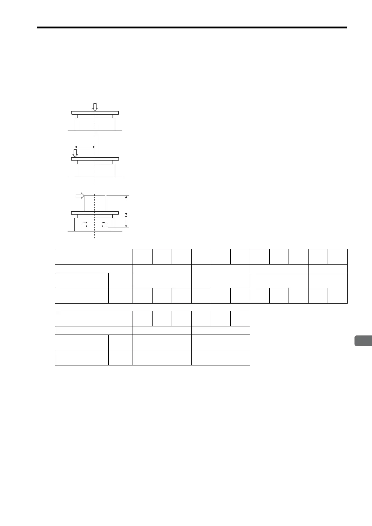
The loads applied while a servomotor is running are roughly classified in the following patterns. Design the
machine so that the thrust load and moment load will not exceed the values in the table.
Note: For small-capacity series SGMCS Servomotors (02B to 35E), set dimensions A to 0 (zero).
F
Where F is external force,
Thrust load: Fa = F + Load mass
Moment load: M = F × L
F
L
Where F is external force,
Thrust load: Fa = F + Load mass
Moment load: M=0
F
L
Where F is external force,
Thrust load: Fa = Load mass
Moment load: M = F × (L + A)
See the table below for the dimension A of each
servomotor model.
A
Servomotor Model
SGMCS-
02B 05B 07B 04C 10C 14C 08D 17D 25D 16E 35E
Dimensions A Units: mm
0000
Allowable Thrust
Load Fa
(N)
1500 3300 4000 11000
Allowable Moment
Load M
(N
m)
40 50 64 70 75 90 93 103 135 250 320
Servomotor Model
SGMCS-
45M 80M 1AM 80N 1EN 2ZN
Dimensions A Units: mm
33 37.5
Allowable Thrust
Load Fa
(N)
9000 16000
Allowable Moment
Load M
(N
m)
180 350

 Loading...


