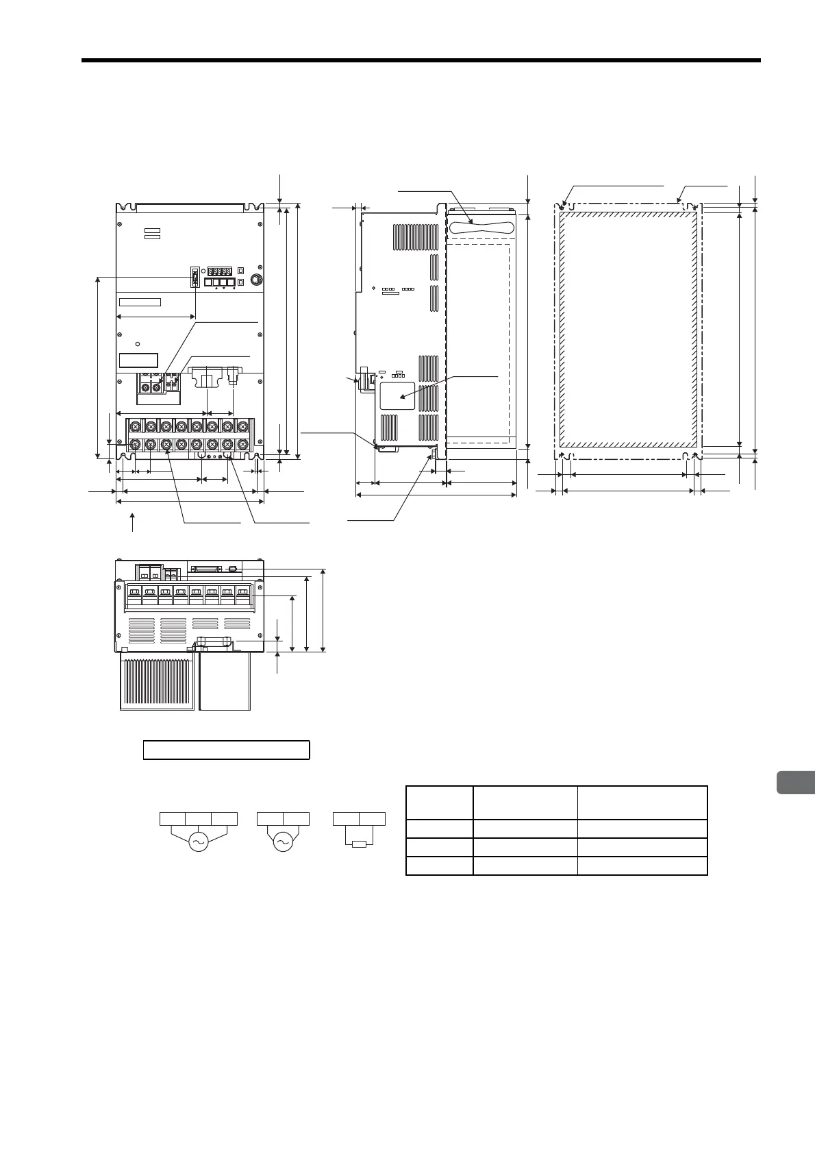
4.9 Dimensional Drawings of Duct-ventilated SERVOPACK Model
4-31
4
SERVOPACK Specifications and Dimensional Drawings
4.9.2 Three-phase 200 V: 11.0 kW/15.0 kW (1AADA-P/1EADA-P)
17
34
126
122
282
Regenerative
resistor/
control circuit
terminal
Main circuit
terminal
10
18.5
413
18.5
20
99
132
146
9
(11)
7.5
435
415
(7.5)
4.5
8
235
244
(4.5)
(8)
CN3
CN8
CN5
SERVOPACK 200V
SGDM-
Ve r.
YASK AWA
CN1 CN2
CHARGE
E
P1 B r t
L1 L2 L3 +1 - U V
140
160
46
27
34
45
151
12.5
235
7
(12.5)
260
(7.5)
(7.5)
450
435
Regenerative
Resistor terminal
M6
26.5
320
POWER
MODE/SET
DATA/
BATTERY
Externals
Punched hole
Mounting Hole Diagram
4×M6 screw holes
Cooling fan
Ground
terminal M8
Ground
terminal
Nameplate
Main circuit
terminal M8
Control circuit
terminal M4
A
View A
Units: mm
Approx. mass: 22 kg
External Terminal Connector
SERVOPACK Connector
Connector
Symbol
SERVOPACK
Connector Model
Manufacturer
CN1 10250-52A2JL Sumitomo 3M Co., Ltd.
CN2 53460-0611 Molex Japan Co., Ltd.
CN3 10214-52A2JL Sumitomo 3M Co., Ltd.
L1C L2CL2 L3L1
External
regenerative
resistor
B1 B2
200 VAC
50/60 Hz
Three-phase
200 VAC
50/60 Hz
Single-phase
Main circuit
power supply
Control power
supply

 Loading...


