4 SERVOPACK Specifications and Dimensional Drawings
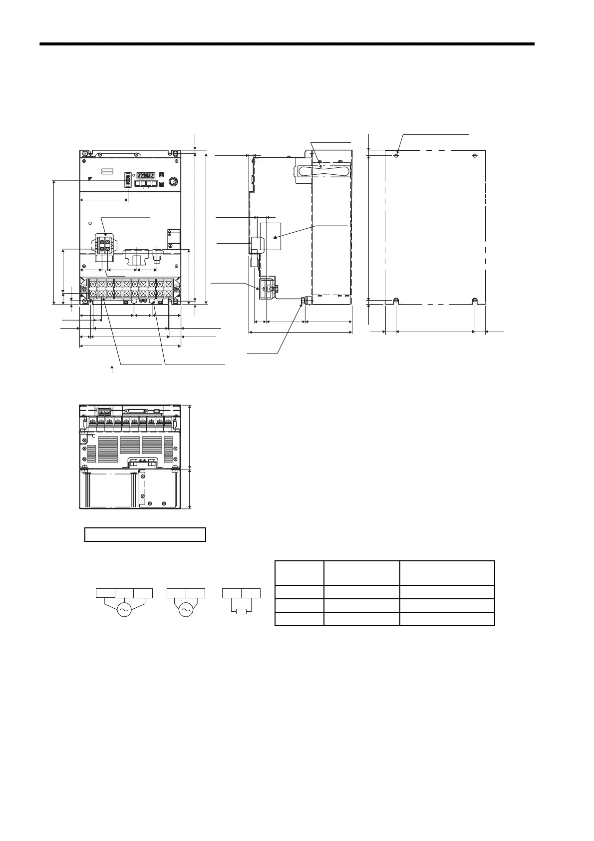
4.7.7 Three-phase 200 V: 6.0 kW/7.5 kW (60ADA to 75ADA)
4-22
4.7.7 Three-phase 200 V: 6.0 kW/7.5 kW (60ADA to 75ADA)
Cooling fan
107
27
10
21
87.5
Main circuit
terminal
Control
circuit
terminal
Max. 235
25
(28.3)
(25)
30.5
171
180
Max. 230
25
9
41
123.5
(65.6)
19
Control circuit
terminal
M4
100.5
51
66
12.5
46
125
282.6
Main circuit
terminal M6
Max. 350
7.5
335
7.5
A
View A
L1 L2 L3
UB2B1+
-
VW
!
ෂ㒾
WARNING
MODE/SET DATA /
Ve r.
POWER
BATTERY
CHARGE
CN2CN1
CN3
110
CN5
CN8
SGDM-
90
145
SERVOPARK 200V
YASKAWA
335
7.5
(7.5)
180
25
(25)
Ground terminal
M8
Nameplate
Mounting Hole Diagram
4×M6 screw holes
Ground
terminal
Units: mm
Approx. mass: 14.3 kg
External Terminal Connector
SERVOPACK Connector
Connector
Symbol
SERVOPACK
Connector Model
Manufacturer
CN1 10250-52A2JL Sumitomo 3M Co., Ltd.
CN2 53460-0611 Molex Japan Co., Ltd.
CN3 10214-52A2JL Sumitomo 3M Co., Ltd.
L1C L2CL2 L3L1
External
regenerative
resistor
B1 B2
200 VAC
50/60 Hz
Three-phase
200 VAC
50/60 Hz
Single-phase
Main circuit
power supply
Control power
supply

 Loading...


