5.2 Servomotor Main Circuit Wire Size and Connectors
5-9
5
Specifications and Dimensional Drawings of Cables and Peripheral Devices
5.2.2 SGMAH and SGMPH Servomotor Connectors for Standard Environments
The SGMAH and SGMPH servomotors do not conform to the IEC’s IP67 classification (IP67 Protective Con-
struction Standard) and the European Safety Standards.
(1) 30 to 750 W SGMAH Servomotor Connector Kit
(2) 100 W to 1.5 kW SGMPH Servomotor Connector Kit
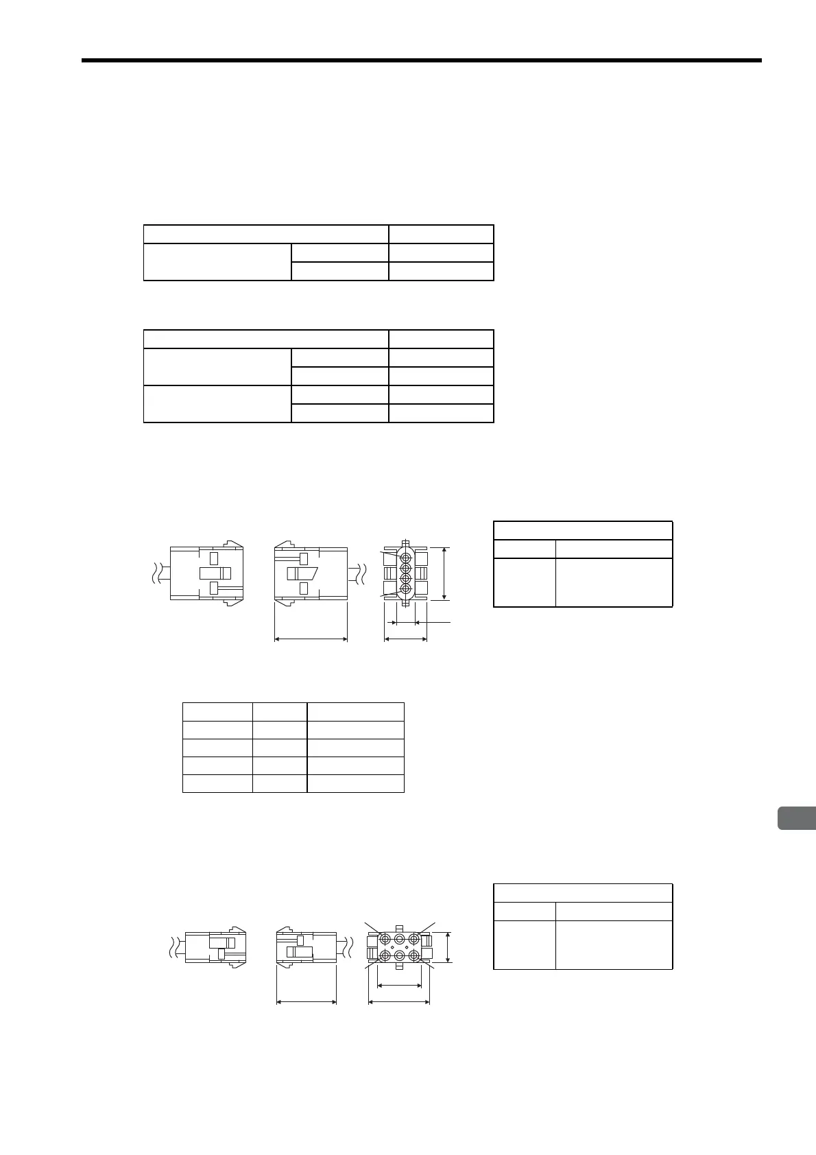
(3) 30 to 750 W SGMAH and 100 to 750 W SGMPH Servomotors Without Brakes
(a) Connector Type: JZSP-CMM9-1
(b) Connector Pin Arrangement
(4) 30 to 750 W SGMAH and 100 to 750 W SGMPH Servomotors With Brakes
(a) Connector Type: JZSP-CMM9-2
Applicable Servomotor Models Type
100 V: 30 to 200 W
200 V: 30 to 750 W
Without brakes JZSP-CMM9-1
With brakes JZSP-CMM9-2
Applicable Servomotor Models Type
100 V: 100 W and 200 W
200 V: 100 to 750 W
Without brakes JZSP-CMM9-1
With brakes JZSP-CMM9-2
200 V: 1.5 kW
Without brakes JZSP-CMM9-3
With brakes JZSP-CMM9-4
Type
Cap 350780-1
Socket
350570-3 or
350689-3
Soldered type
Pin No. Signal Lead Color
1Phase U Red
2 Phase V White
3Phase W Blue
4 FG Green/Yellow
14.7
27.4
7.6
4
1
27.7
Connector on
servomotor
Servomotor main
circuit connector
Units: mm
Type
Cap 350781-1
Socket
350570-3 or
350689-3
Soldered type
28.4
20.3
6
3
1
4
27.4
14
Connector on
servomotor
Units: mm
Servomotor main
circuit connector

 Loading...


