12.2 Connection to Host Controller
12-21
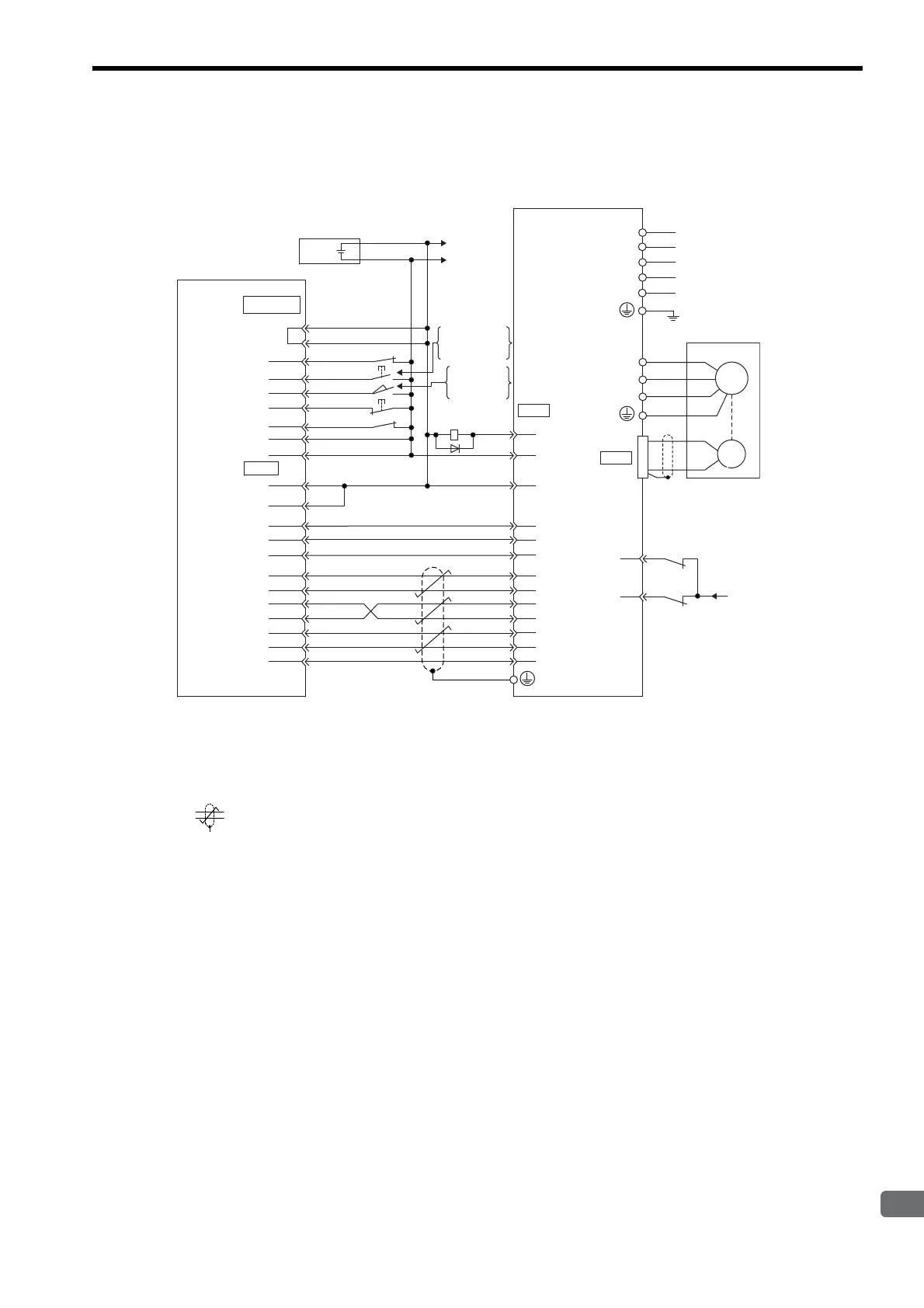
12.2.7 Example of Connection to OMRON’s Position Control Unit C500-NC221
(SERVOPACK in Speed Control Mode)
* 1. The ALM signal is output for approximately two seconds when the power is turned ON. Take this into consid-
eration when designing the power ON sequence. The ALM signal actuates the alarm detection relay 1Ry to
stop main circuit power supply to the SERVOPACK.
* 2. Connect the I/O cable’s shield wire to the connector shell.
* 3. represents twisted-pair wires.
Note: Only signals applicable to OMRON’s C500-NC221 position control unit and Yaskawa’s SGDM SERVO-
PACK are shown in the diagram.
42
43
3Ry
1Ry
4Ry
3Ry
19
36
35
20
1
34
33
CCWLX
STPX
ORGX
EMGX
DC GND
DC GND
CWLX
X-AG
X-OUT
OUT-1X
+24V
0V
X-B
X-C
X-A
+24V
+
-
EXT IN
+24V
M/D
ALM+
ALM -
V-REF(T-REF)
SG
P-OT
N-OT
4Ry
3(13)
4(14)
5(15)
6(16)
1
11
2(12)
9
8
6(22)
1(17)
15(13)
16(14)
4(20)
5(21)
7(23)
8(24)
9(25)
3(19)
5(9)
6(10)
31
32
47
40
∗1
∗2
/S-ON
+24VIN
∗3
11
12
X-/B
X-/C
X-/A
0
24V
+24V
PAO
SG
PCO
PBO
/PAO
/PCO
/PBO
0
24V
I/O power supply
X-axis (Y-axis)
Position control
unit C500-NC221
manufactured by
OMRON
ON when
positioning
is canceled.
ON when
proximity
is detected.
SGDM SERVOPACK
Connector
∗2
shell
CN2
CN1
L1C
L3
L2
L1
L2C
W
V
A(1)
B
(2)
C
(3)
D
(4)
U
Servomotor
M
PG

 Loading...


