12 Appendix
12.2.4 Example of Connection to MEMOCON GL60/70 Series Positioning Module B2813 (SERVOPACK in Position Control Mode)
12-18
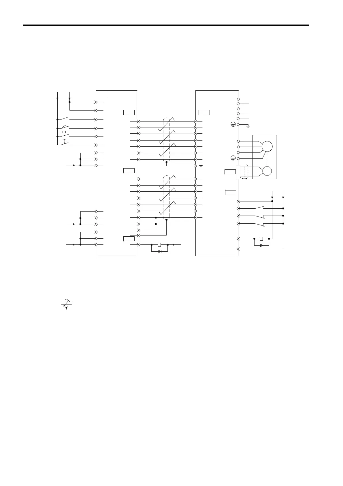
12.2.4 Example of Connection to MEMOCON GL60/70 Series Positioning Module
B2813 (SERVOPACK in Position Control Mode)
* 1. The ALM signal is output for approximately two seconds when the power is turned ON. Take this into consid-
eration when designing the power ON sequence. The ALM signal actuates the alarm detection relay 1Ry to
stop main circuit power supply to the SERVOPACK.
* 2. Set parameter Pn200.0 to 1.
* 3. Connect the shield wire to the connector shell.
* 4. represents twisted-pair wires.
1Ry
0
24
V
+24V
+12V
+5V
0V
ERROR
FG
PA
PB
0V
PC
MEMOCON GL60/70 Series B2813
manufactured by Yaskawa
START
STOP
PAO
SG
PCO
PBO
+24VIN
/S-ON
P-OT
N-OT
ALM+
ALM -
3Ry
4Ry
1
33
35
20
47
46
45
2
3
49
48
12
11
10
50
19
18
17
16
3
2
1
15
14
36
20
+12V
19
36
35
20
34
33
43
42
40
47
32
31
PULSE
0V
CLR
SIGN
PULSE
SG
CLR
SIGN
24
6
5
38
21
22
23
2
14
15
12
11
8
7
2Ry
/PULSE
/CLR
/SIGN
/PA
/PB
/PC
0V
0V
/PULSE
/CLR
/SIGN
/PAO
/PCO
/PBO
SERVO
NORMAL
DECELERATION
LS
Connector shell
CN2
CN1
CN1CN2
CN2
CN1
CN2
L1C
L3
L2
L1
L2C
W
V
A(1)
B
(2)
C
(3)
D
(4)
U
Servomotor
M
PG
0
24
V
+24V
1Ry
∗1
∗2
∗3
∗4
SGDM SERVOPACK

 Loading...


