3 Servomotor Specifications and Dimensional Drawings
3.9.2 Mechanical Tolerance
3-42
3.9.2 Mechanical Tolerance
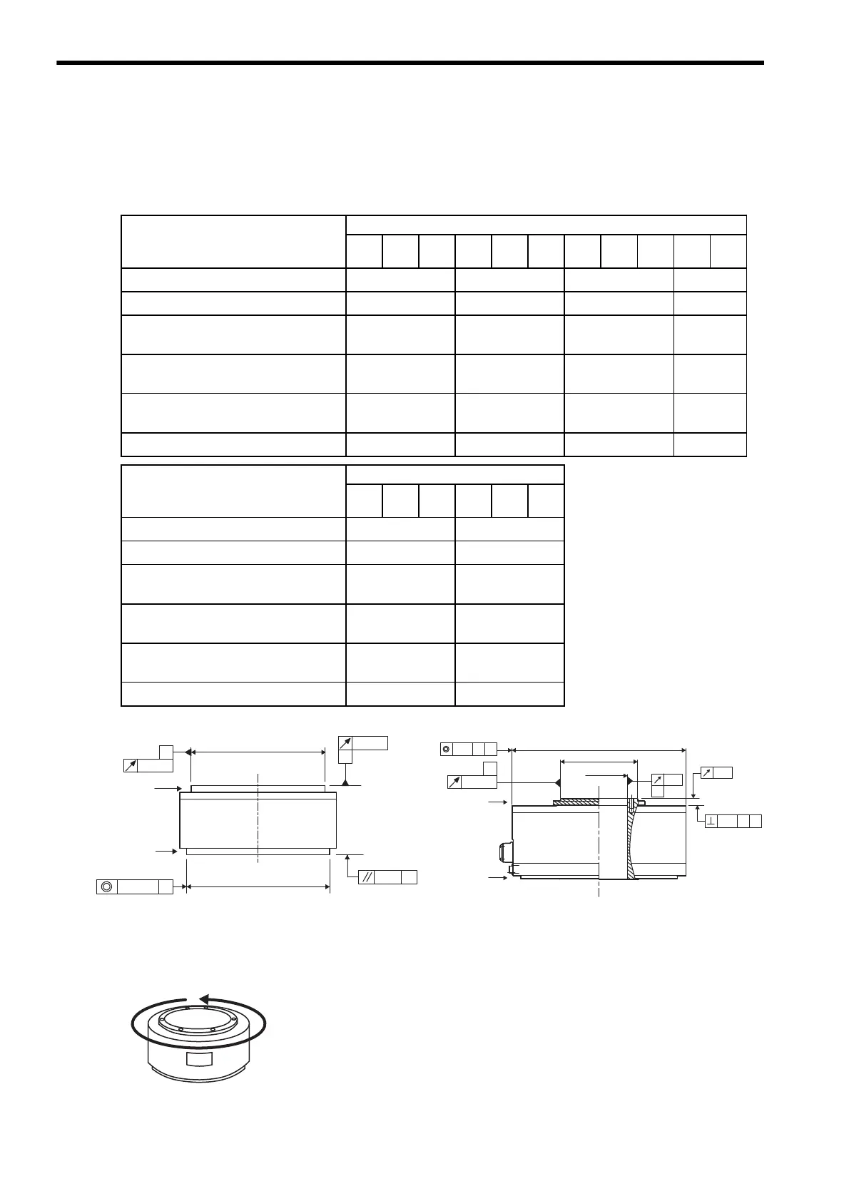
The following table shows tolerances for the servomotor’s output shaft and installation area. See the dimensional
drawing of the individual servomotor for more details on tolerances.
3.9.3 Direction of Servomotor Rotation
Positive rotation of the servomotor is counterclockwise when viewed from the load.
Mechanical Tolerance
Tol erance T. I . R.
(Total Indicator Reading)
Units: mm
Servomotor Model SGMCS-
02B 05B 07B 04C 10C 14C 08D 17D 25D 16E 35E
cRun-out of the surface of the shaft
0.02 0.02 0.02 0.02
dRun-out at the end of the shaft
0.04 0.04 0.04 0.04
ePerpendicularity between the
flange face and output shaft
0.07 0.07 0.08 0.08
fCoaxiality of output axis and
mounting socket joint
0.07 0.07 0.08 0.08
gRight angle between flange face
and output shaft
−−−−
hReference figure
Fig.1 Fig.1 Fig.1 Fig.1
Tol erance T. I . R.
(Total Indicator Reading)
Units: mm
Servomotor Model SGMCS-
45M 80M 1AM 80N 1EN 2ZN
cRun-out of the surface of the shaft
0.02 0.02
dRun-out at the end of the shaft
0.04 0.04
ePerpendicularity between the
flange face and output shaft
−−
fCoaxiality of output axis and
mounting socket joint
0.08 0.08
gRight angle between flange face
and output shaft
0.08 0.08
hReference figure
Fig.2 Fig.2
Fig.1 Fig.2
B
A
A
B
Drive end
φ
φ
φ
Opposite
drive end
φ
φ
φ
B
AB
AB
A
Drive end
Opposite
drive end

 Loading...


