12.2 Connection to Host Controller
12-23
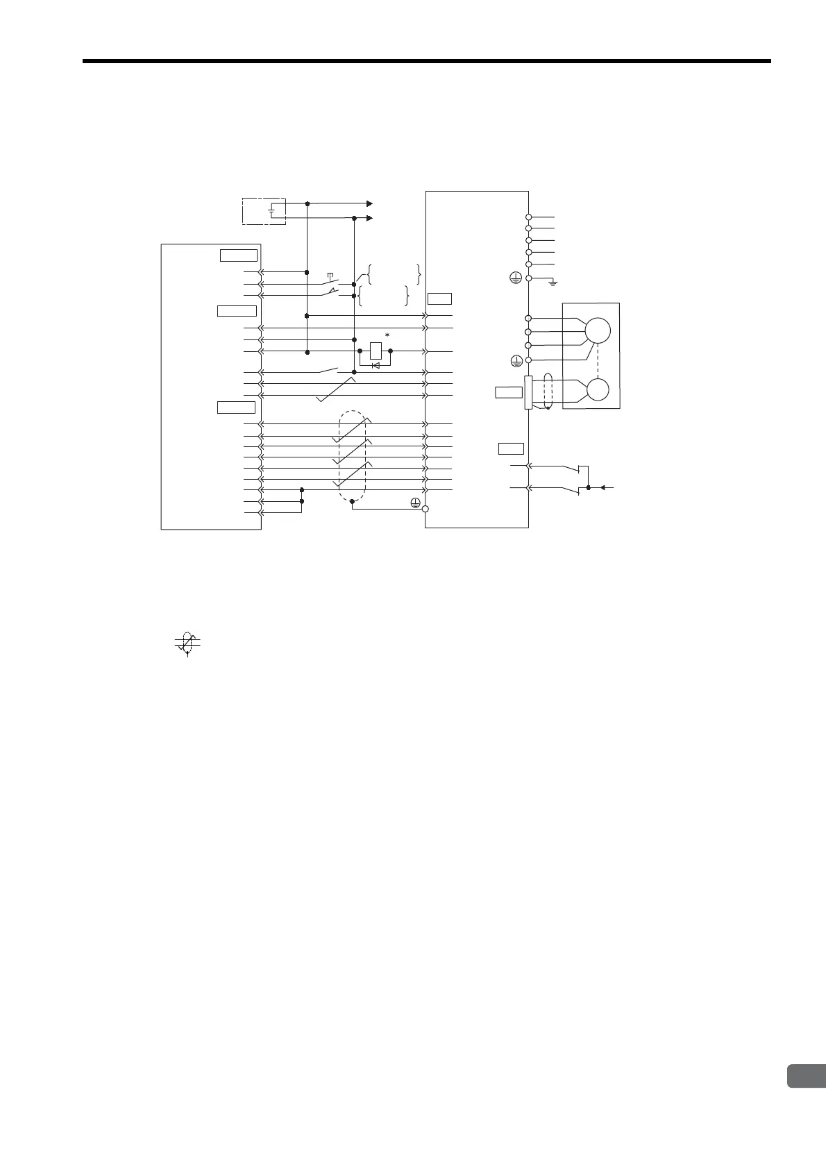
12.2.9 Example of Connection to MITSUBISHI’s AD72 Positioning Unit
(SERVOPACK in Speed Control Mode)
* 1. The ALM signal is output for about two seconds after the power is turned ON. Take this into consideration
when designing the power ON sequence. The ALM signal actuates the alarm detection relay 1Ry to stop the
main circuit power supply to the SERVOPACK.
* 2. Pin numbers are the same both for X-axis and Y-axis.
* 3. Connect the connector wire to the connector shell.
* 4. represents twisted-pair wires.
Note: Only signals applicable to Mitsubishi’s AD72 Positioning Unit and Yaskawa’s SGDM SERVOPACK are
shown in the diagram.
43
42
1Ry
+
-
+24V
I/O power supply
0
24
V
+24 V
CONT
SERVO
CN1
ENCO
CN1
STOP
DOG
SV-ON
READY
PULSE A
PULSE C
PULSE B
0V
0V
0V
∗
2
1
3
2
1
3
2
4
6
5
4
7
5
8
11
10
3
9
6
1
+24V-IN
P-OT
N-OT
ALM+
ALM-
V-REF(T-REF)
SG
PAO
SG
/PCO
PCO
/PBO
PBO
/PAO
47
32
31
40
1
20
19
34
33
36
35
5
(9)
6
(10)
/S-ON
1Ry
∗
4
0
24
V
Positioning unit AD72
manufactured
by Mitsubishi
SGDM SERVOPACK
Speed reference
ON when
positioning is
canceled.
ON when
proximity is
detected.
∗3
Connector
shell
CN2
L1C
L3
L2
L1
L2C
W
V
A(1)
B
(2)
C
(3)
D
(4)
U
Servomotor
M
Control
power supply
PG
Main circuit
power supply

 Loading...


