4 SERVOPACK Specifications and Dimensional Drawings
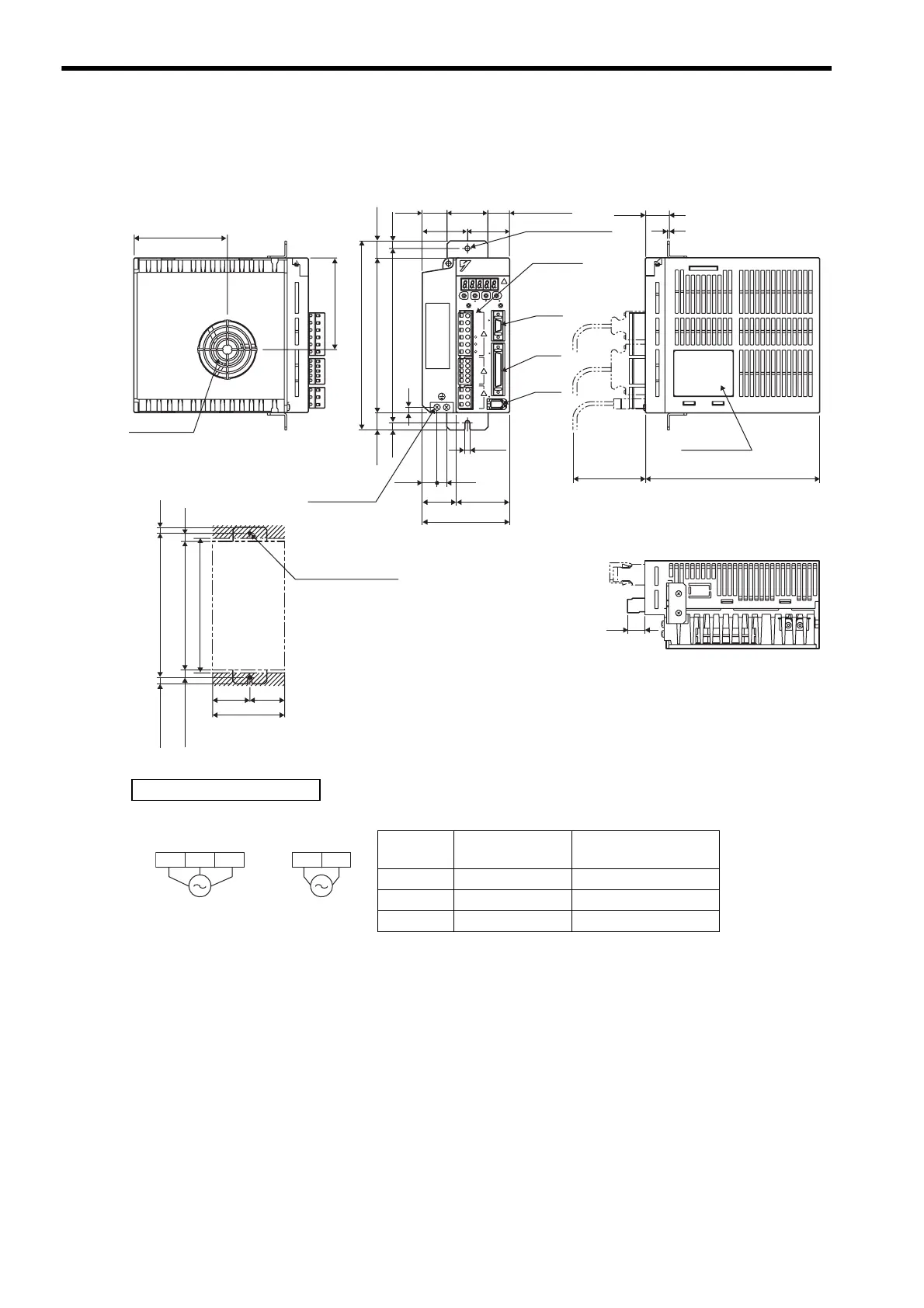
4.8.3 Three-phase 200 V: 500 W/750 W/1.0 kW (05AD-R to 10AD-R, 05ADA-R to 10ADA-R)
4-26
4.8.3 Three-phase 200 V: 500 W/750 W/1.0 kW
(05AD-R to 10AD-R, 05ADA-R to 10ADA-R)
Mounting Hole Diagram
96.2
180(75)
17
7.5
(10)
160
90
180
94.4
7.5
7.5
195
160
17.5
17.5
6
90
55
35
10
15
5
42
46.5 43.5
25.5
2
24.5
φ
46.5
Cooling fan
(7.5)
CN3
CN2
CN1
YAS KAWA
YAS KAWA
SERVOPACK200V
SGDM-
5 hole
180±0.5
Min.168
2×M4 screw holes
(43.5)
10
(22.5)
CHANGE
MODE/SET
DATA/
POWER
L1
C
N
3
L2
L3
L2C
B1
B2
B3
U
V
W
L1C
+ 1
+ 2
C
N
1
C
N
2
Ground
terminal
2×M4 screws
Terminal
block
Nameplate
(Mounting pitch)
Units: mm
Approx. mass: 1.9 kg
External Terminal Connector
SERVOPACK Connector
Connector
Symbol
SERVOPACK
Connector Model
Manufacturer
CN1 10250-52A2JL Sumitomo 3M Co., Ltd.
CN2 53460-0611 Molex Japan Co., Ltd.
CN3 10214-52A2JL Sumitomo 3M Co., Ltd.
Three-phase
200 VAC
50/60 Hz
Single-phase
200 VAC
50/60 Hz
L2 L3L1 L1C L2C
Main circuit
power supply
Control power
supply

 Loading...


