4 SERVOPACK Specifications and Dimensional Drawings
4.3.1 Single-phase 200 V, 30 W to 400 W, and 100 V, 30 W to 200 W Models
4-8
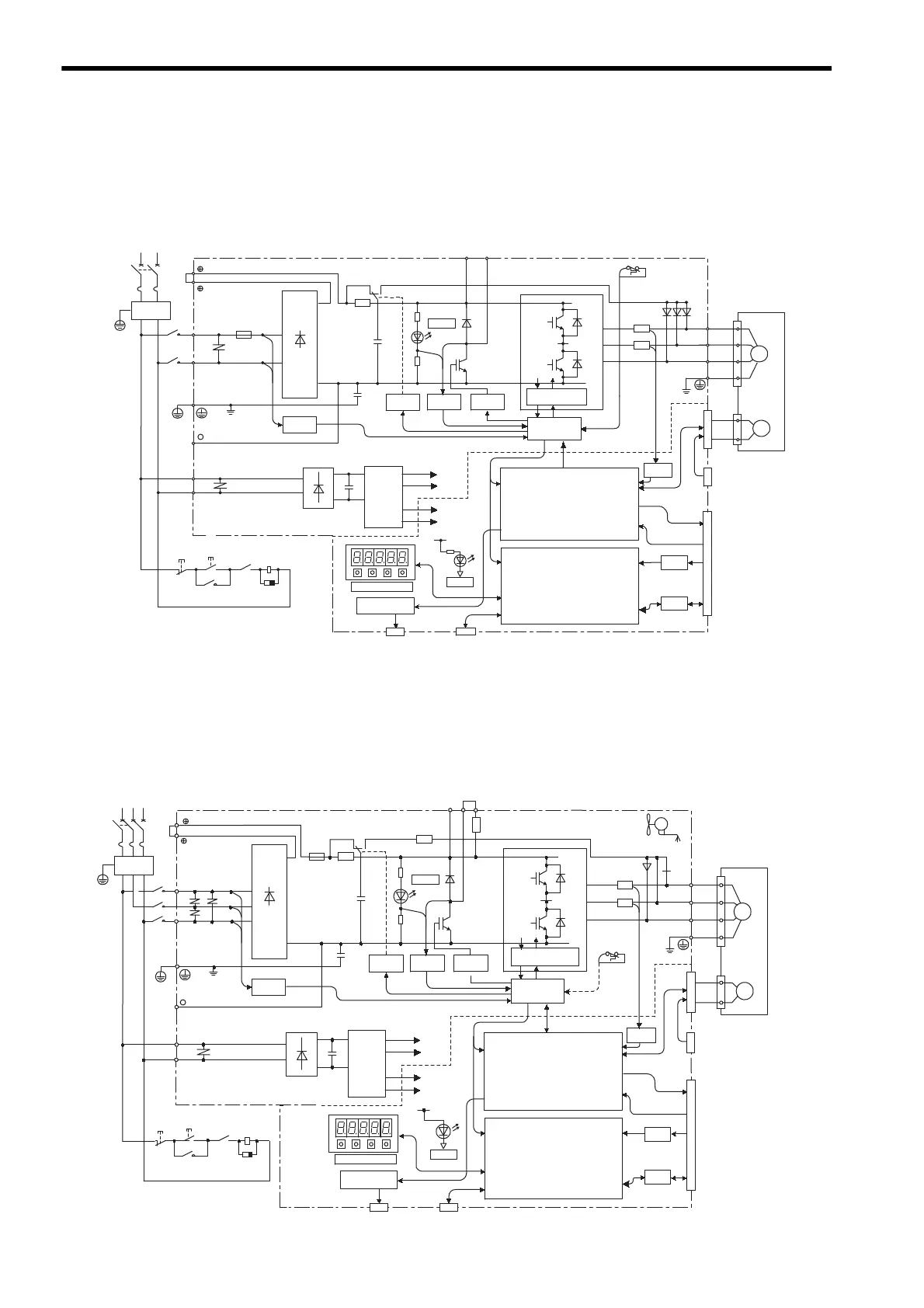
4.3 SERVOPACK Internal Block Diagrams
4.3.1 Single-phase 200 V, 30 W to 400 W, and 100 V, 30 W to 200 W Models
4.3.2 Three-phase 200 V, 500 W to 1.5 kW Models
CHARGE
POWER
A/D
I/O
1KM
L1
L2
XX1
FU1
L1C
L2C
1KM
~
~
+
-
R
T
N1
TR1
C1
+5 V
0 V
CN5
CN3
+15 V
B1 B2
P2
N2
U
V
W
CN1
CN2
D2 D3 D4
THS1
PG
M
R7
R8
±5 V
+5 V
±12 V
CN8
1
PM1-1
D1
RY1
PM1-2
2
+
-
+
-
U
V
W
1KM
1RY
Reference pulse input
Speed/torque
reference input
Sequence I/O
Single-phase 200 to 230 V
(50/60 Hz)
+10%
-15%
+10%
-15%
Single-phase 100 to 115 V
Noise
filter
Voltage
sensor
Power
OFF
Power
ON
Open during
servo alarm (1RY)
Surge
absorber
∗ The supply voltage for 100V, 30 to 200W is 100 to 115V (50/60 Hz).
Relay
drive
Gate
drive
Voltage
sensor
Gate drive over-
current protector
Interface
Current
sensor
Servomotor
Analog voltage
converter
Panel operator
Analog monitor
output for
supervision
Digital operator or
personal computer
CPU
(Position/speed
calculation, etc.)
ASIC
(PWM control, etc.)
PG output
For battery connection
DC / DC
converter
+10%
-15%
THS1
R2
FU1
FAN1
±12V
1
2
1KM
L1
L3
L2
XX1
XX2
XX3
L1C
L2C
R
T
P
N
S
~
~
+
-
+
-
C1
RY1
+
-
CHARGE
B1 B2 B3
P
N
POWER
+5 V
0 V
CN5
CN3
+15 V
±5 V
+5 V
±12 V
U
V
W
A/D
I/O
CN1
CN2
PG
M
CN8
D2 D3 D4
U
V
W
1KM
1KM
1KM
PG output
Reference pulse input
Speed/torque
reference input
Sequence I/O
∗ When 0.5 kW to 1.0 kW
models are used.
Single/Three-phase 200 to 230 V
(50/60 Hz)
+10%
-15%
Noise
filter
Voltage
sensor
Relay
drive
Gate
drive
Voltage
sensor
Gate drive over-
current protector
Interface
Current
sensor
Servomotor
Power
OFF
Power
ON
Open during
servo alarm (1RY)
Surge
absorber
Analog voltage
converter
Panel operator
Analog monitor
output for
supervision
Digital operator or
personal computer
CPU
(Position/speed
calculation, etc.)
ASIC
(PWM control, etc.)
For battery connection
DC / DC
converter

 Loading...


