8 Operation
8.4.1 Interface Circuits
8-30
8.4.1 Interface Circuits
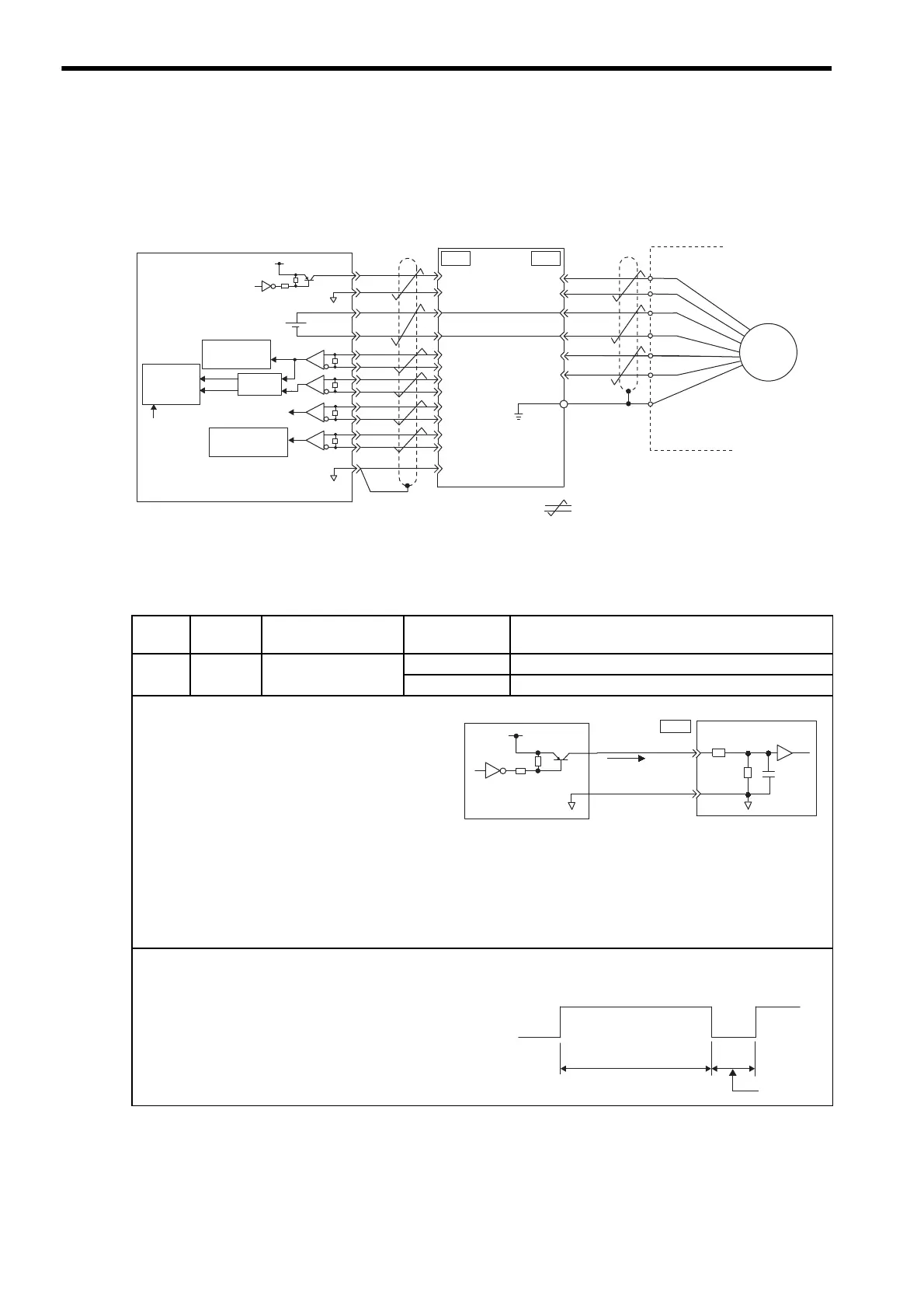
The following diagram shows the standard connections for a an absolute encoder mounted to a servomotor. The
connection cables and wiring pin numbers depend on the servomotor. For details, refer to chapter 5 Specifica-
tions and Dimensional Drawings of Cables and Peripheral Devices.
• SEN Signal Connection
Host controller
Battery
SERVOPACK
Encoder
Serial interface
circuit
Line driver
Edge
detection
Up/down
counter
Clear
Shield (shell)
Connector
shell
Applicable line receiver:
Texas Instruments's SN75175 or KM3486
Terminating resistance R: 220 to 470 Ω
R
PG5V
PG0V
BA
PS
/PS
T (+)
BAT ( - )
BAT(-)
PCO
/PCO
PBO
/PBO
PAO
/PAO
BAT(+)
SEN
SG
R
R
PA
PB
PC
PS
+5V
7406
0V
+
-
4
2
21
22
33
34
35
36
19
1
20
CN1
1
2
3
4
6
5
CN2
UP
DOWN
SG
0V
㧦Represents twisted-pair wires.
For wiring pin numbers, refer to chapter 5
Specifications and Dimensional Drawings of
Cables and Peripheral Devices
R
PSO
/PSO
48
49
PG
∗1㧚
∗2㧚
∗1∗1
∗2
Serial interface
circuit
Type Name Connector
Pin Number
Setting Meaning
Input SEN CN1-4 OFF (low level) Input when power is turned ON
ON (high level) Input at absolute data request
• This input signal is required to output absolute data
from the SERVOPACK.
• When the SERVOPACK main circuit power supply
turns OFF, input the SEN signal at a low level.
• Let at least three seconds elapse after turning ON the
power before changing the SEN signal to high level.
• When the SEN signal changes from low level to high
level, the multiturn data and initial incremental
pulses are output.
Until these operations have been completed, the ser-
vomotor cannot be turned ON regardless of the status
of the servo ON signal (/S-ON).
• The panel operator display will also remain “b.b”.
Refer to 8.4.6 Absolute Encoder Reception Sequence.
IMPORTANT
1. Maintain the high level for at least 1.3 seconds when the
SEN signal is turned OFF and then ON, as shown in the fig-
ure on the right.
2. When the SERVOPACK main circuit power supply turns
OFF, input the SEN signal at a low level.
4.7 k
SEN
4
CN1
SG
2
+5V
0V
100 Ω
Ω
0V
0.1 μ(
Host controller
SERVOPACK
High level:
About 1 mA
7406
or equivalent
We recommend a PNP transistor.
Signal levels
High: 4.0 V min.㧘Low: 0.8 V max.
OFF ON (high level)
1.3 s min.
OFF ON
15 ms min.
SEN signal

 Loading...


