8 Operation
8.11.2 Warning Output (/WARN)
8-76
8.11.2 Warning Output (/WARN)
• Related Parameters
The following parameter is used to select the alarm code output.
8.11.3 Running Output Signal (/TGON)
• Related Parameter
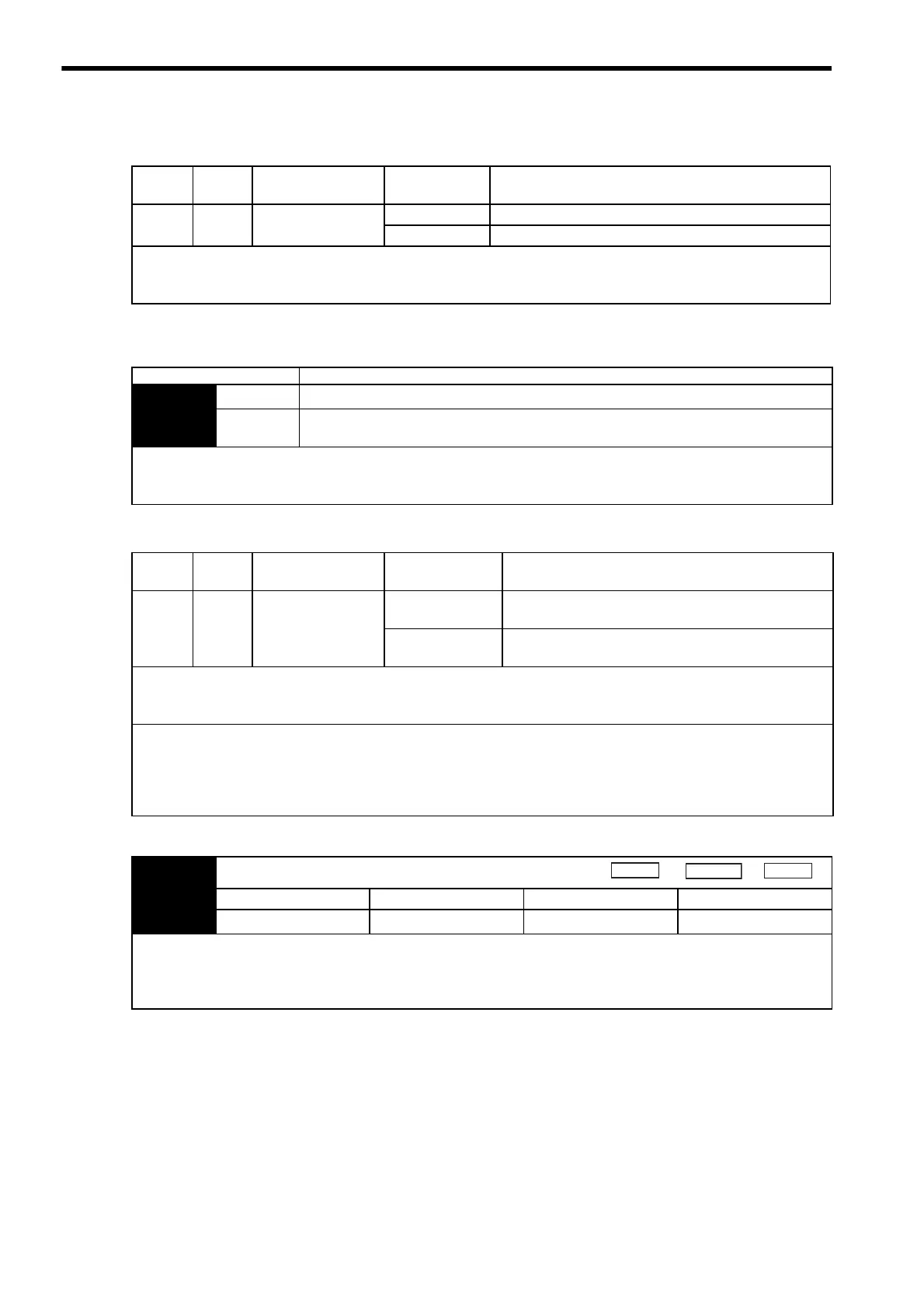
Type Signal
Name
Connector
Pin Number
Setting Meaning
Output /WARN Must be allocated ON (high level) Normal state
OFF (low level) Warning state
This output signal displays warnings before an overload (A.71) or regenerative overload (A.32) alarm is output.
For use, the /WARN signal must be allocated with parameter Pn50F. For details, refer to 7.3.3 Output Circuit Signal Allo-
cation.
Parameter Description
Pn001
n.0
Outputs alarm codes alone for alarm codes ALO1, ALO2, and ALO3.
n.1
Outputs both alarm and warning codes for alarm codes ALO1, ALO2, and ALO3, and out-
puts an alarm code when an alarm occurs.
• Refer to 8.11.1 Servo Alarm Output (ALM) and Alarm Code Output (ALO1, ALO2, ALO3) for alarm code descriptions.
• Refer to 11.1.2 Warning Display for the ON/OFF combinations of ALO1, ALO2, and ALO3 when a warning code is out-
put.
Type Signal
Name
Connector
Pin Number
Setting Meaning
Output /TGON CN1-27, 28
(Factory setting)
ON (low level) Servomotor is operating (Motor speed is above the set-
ting in Pn502).
OFF (high level) Servomotor is not operating (Motor speed is below the
setting in Pn502).
This signal is output to indicate that the servomotor is currently operating above the setting in parameter Pn502.
The /TGON signal can be allocated to another output terminal with parameter Pn50E. For details, refer to 7.3.3 Output Cir-
cuit Signal Allocation.
IMPORTANT
• If the brake signal (/BK) and running output signal (/TGON) are allocated to the same output terminal, the /TGON signal
will go to low level at the speed at which the movable part drops on the vertical axis, which means that the /BK signal will
not go to high level. (This is because signals are output with OR logic when multiple signals are allocated to the same out-
put terminal.). Always allocate /TGON and /BK signals to different terminals.
Pn502 Rotation Detection Level
Setting Range Setting Unit Factory Setting Setting Validation
1 to 10000
1 min
-1
20 Immediately
Set the range in which the running output signal (/TGON) is output in this parameter.
When the servomotor rotation speed is above the value set in the Pn502, it is judged to be servomotor rotating and the run-
ning output signal (/TGON) is output. The rotation detection signal can also be checked on the digital operator. For details,
refer to 7.1.4 Status Display and 7.4.1 List of Monitor Modes.

 Loading...


