6.3 Examples of I/O Signal Connections
6-15
6.3.6 Interface Circuit
This section shows examples of SERVOPACK I/O signal connection to the host controller.
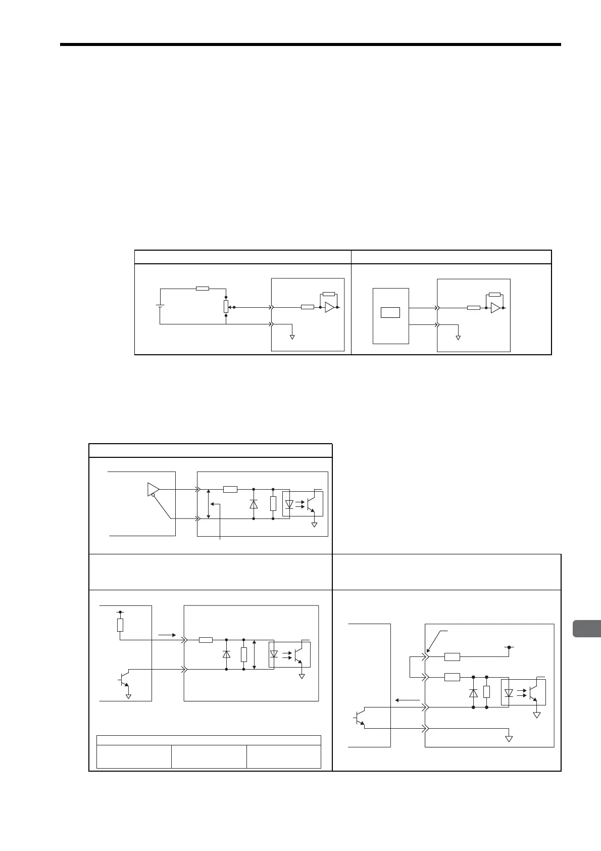
(1) Interface for Reference Input Circuits
(a) Analog Input Circuit
CN1 connector terminals, 5-6: Speed reference input and 9-10: Torque reference input are explained below.
Analog signals are either speed or torque reference signals at the impedance below.
• Reference speed input: About 14 kΩ
• Reference torque input: About 14 kΩ
The maximum allowable voltages for input signals is
±12 V.
(b) Position Reference Input Circuit
CN1 connector terminals, 7-8: Reference pulse input, 11-12: Reference code input and 15-14: Clear input are
explained below.
An output circuit for the reference pulse and position error pulse clear signal at the host controller can be either
line-driver or open-collector outputs. The following shows by type.
Analog Voltage Input Circuit Analog Voltage Input Circuit (D/A)
1.8 k
Ω (1/2 W)min.
25HP-10B
2 k
Ω
3
2
12 V
1
0 V
SG
About 14 kΩ
SERVOPACK
V-REF or
T-REF
0 V
SG
Host controller
About 14 kΩ
SERVOPACK
V-REF or
T-REF
D/A
Line-driver Output Circuit
Open-collector Output, Example 1:
Power Supply Provided by User
Open-collector Output, Example 2:
Using 12-V Power Supply Built into SERVOPACK,
Non-insulated Input
150 Ω
4.7 kΩ
2.8 V
≤
(H level) - (L level)
≤
3.7 V
Applicable line driver
SN75174 manufactured
by Texas Instruments
or the equivalent
Host controller
SERVOPACK
V
F
= 1.5 to 1.8 V
Vcc
Tr1
V
F
R1
i
150 Ω
4.7 kΩ
Use the examples below to set pull-up resistor R1 so the input
current, i, falls between 7 mA and 15 mA.
Application Examples
R1 = 2.2 kΩ with a
Vcc of 24 V
±
5%
R1 = 1 kΩ with a
Vcc of 12 V
±
5%
R1 = 180 Ω with a
Vcc of 5 V
±
5%
Host controller
SERVOPACK
PL1, PL2, PL3 terminals
0 V
SG
+12 V
1.0 kΩ
150 Ω
1.5 V max.
when ON
About
9 mA
Host controller
SERVOPACK

 Loading...


