5.2 Servomotor Main Circuit Wire Size and Connectors
5-19
5
Specifications and Dimensional Drawings of Cables and Peripheral Devices
5.2.7 SGMDH Servomotor (2000 min
-1
) Connectors for Standard Environments
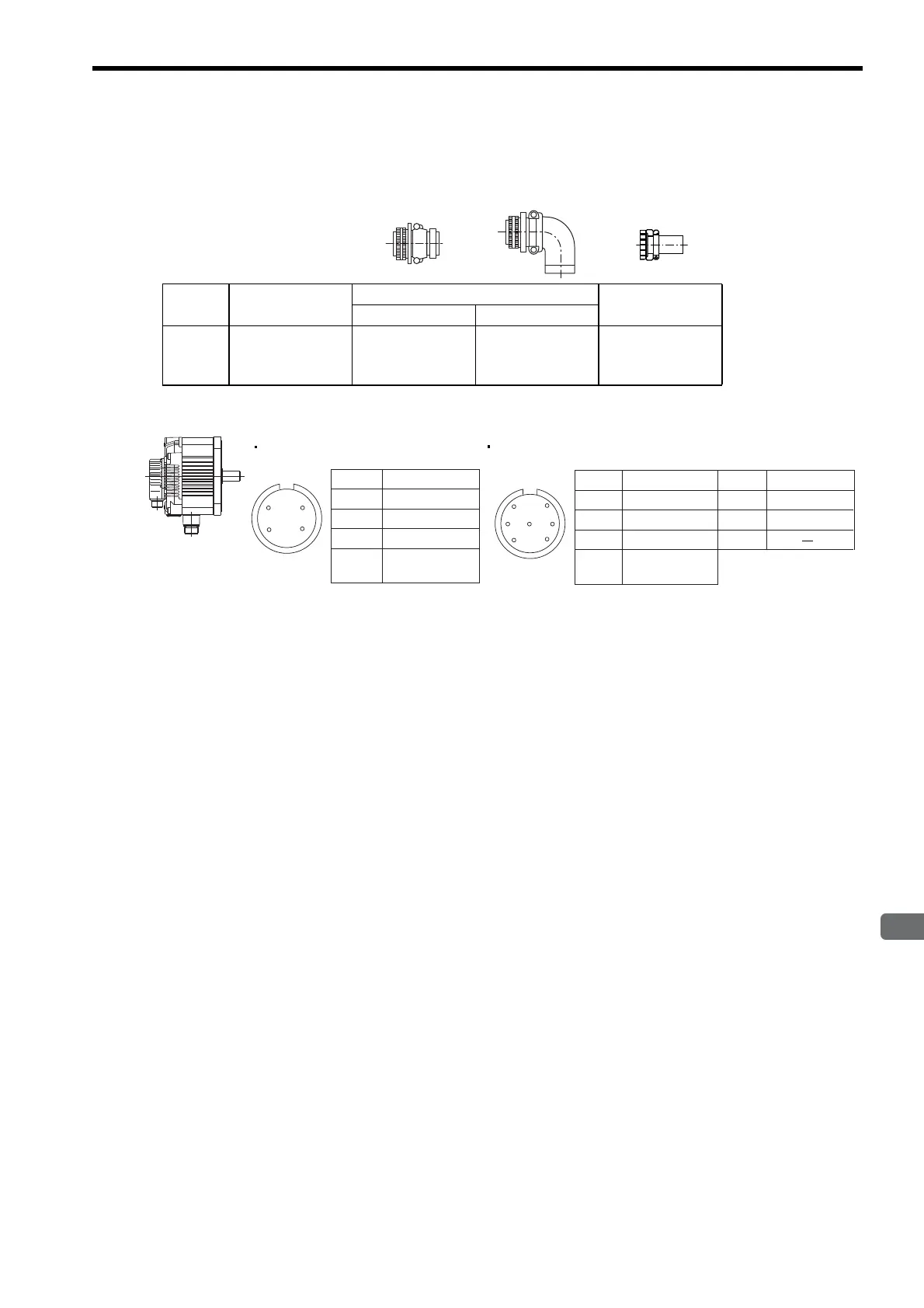
(1) With and Without Holding Brakes
(2) Servomotor Main Circuit Connector Pin Arrangement
Capacity
(kW)
Connector on
Servomotor
Plug
Cable Clamp
Straight L-shaped
2.2
3.2
4.0
MS3102A24-10P MS3106B24-10S MS3108B24-10S MS3057-16A
Servomotor-end
connector
A
B
C
D
Phase U
Phase V
Phase W
FG
(Frame Ground)
Pin No. Signal
E *
F *
G
Brake terminal
Brake terminal
Pin No. Signal
Without Brakes
A
B
C
D
Phase U
Phase V
Phase W
FG
(Frame Ground)
Pin No. Signal
D
B
G
C
AF
E
With Brakes
* No polarity
D
BC
A

 Loading...


