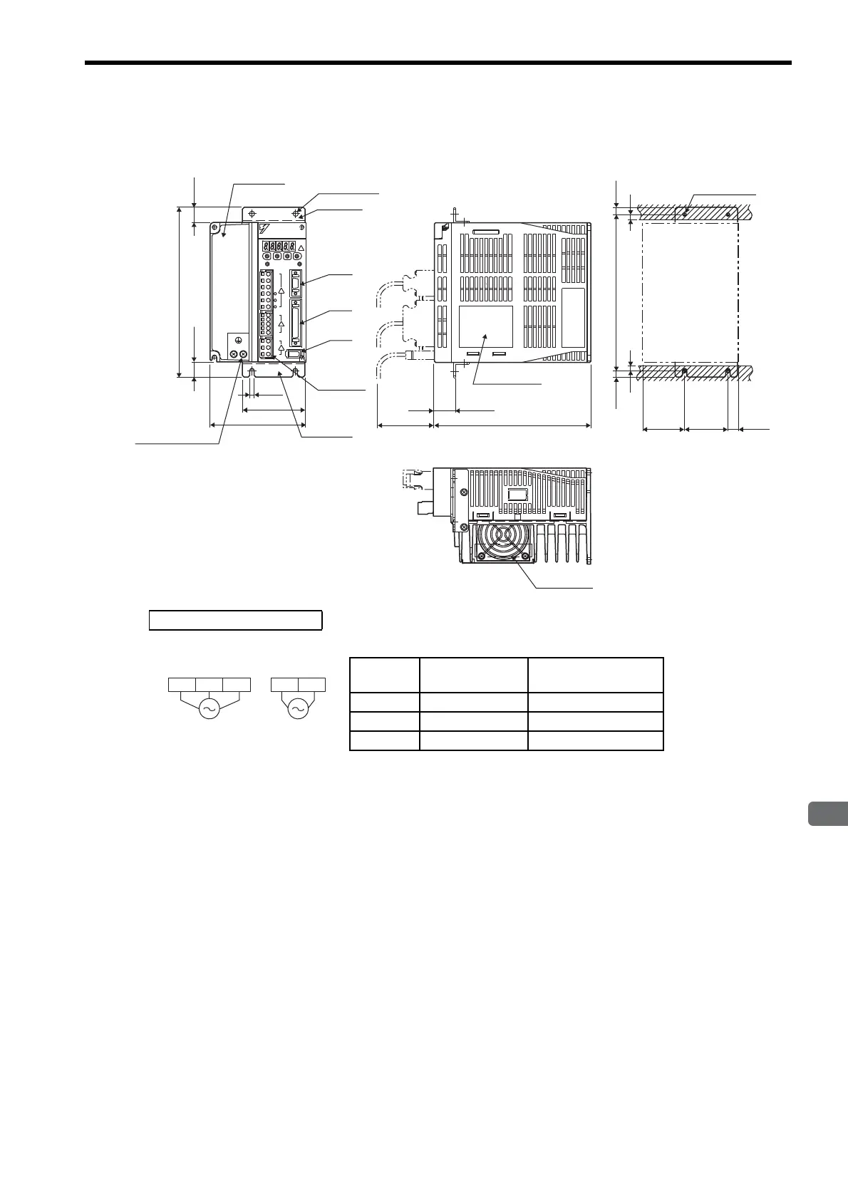
4.8 Dimensional Drawings of Rack-mounted SERVOPACK Model
4-27
4
SERVOPACK Specifications and Dimensional Drawings
4.8.4 Three-phase 200 V: 1.5 kW (15AD-R, 15ADA-R)
Cooling fan
Terminal
block
-
23D1
CN3
CN1
CN2
YAS KAWA
YAS KAWA
SERVOPACK
SGDM-
195
17.5
17.5
72
5
2×φ5 holes
110
180
(75)
7.5
50 ± 0.5
180 ± 0.5
(7.5)
(12)
(48)
24.5
6
6
Heat sink
Flange
Flange
Mounting Hole Diagram
Ground terminal
2×M4 screws
4×M4 screw
Nameplate
(Mounting pitch)
(Mounting pitch)
Units: mm
Approx. mass: 3.0 kg
External Terminal Connector
SERVOPACK Connector
Connector
Symbol
SERVOPACK
Connector Model
Manufacturer
CN1 10250-52A2JL Sumitomo 3M Co., Ltd.
CN2 53460-0611 Molex Japan Co., Ltd.
CN3 10214-52A2JL Sumitomo 3M Co., Ltd.
L1C L2CL2 L3L1
200 VAC
50/60 Hz
Three-phase
200 VAC
50/60 Hz
Single-phase
Main circuit
power supply
Control power
supply

 Loading...


