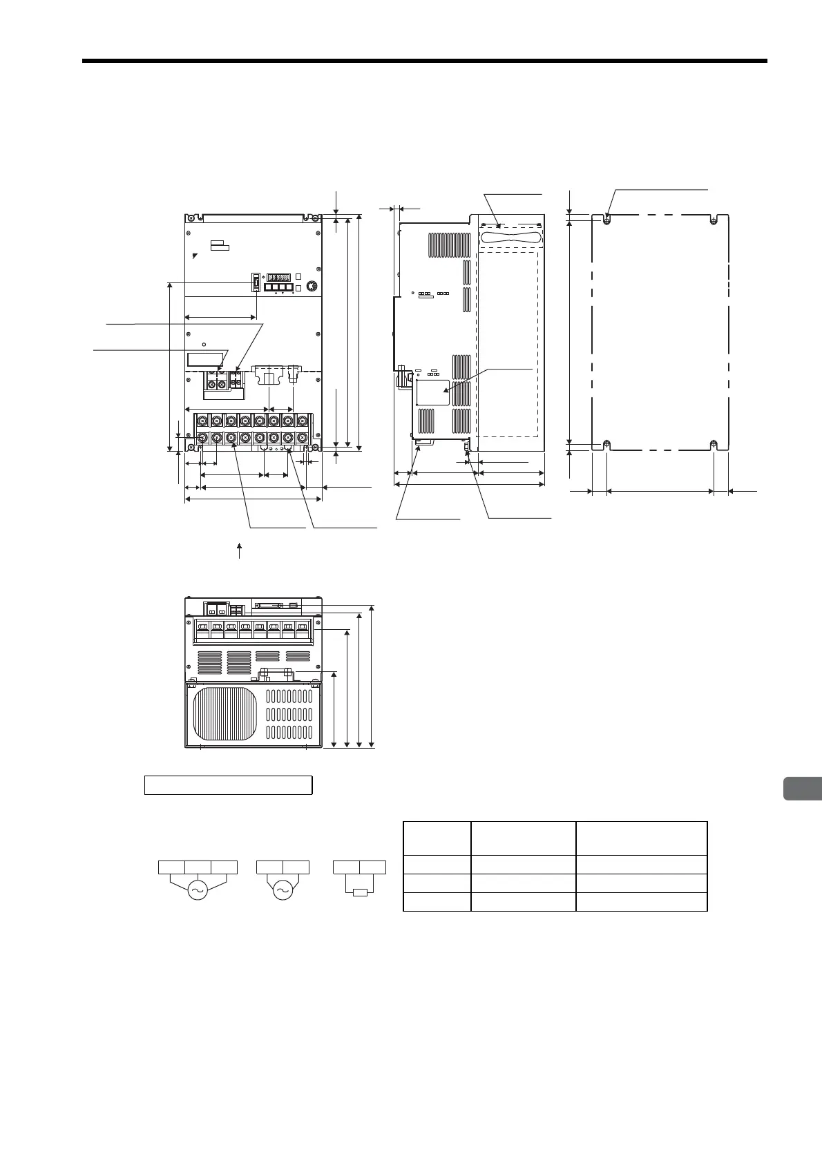
4.7 Dimensional Drawings of Base-mounted SERVOPACK Model
4-23
4
SERVOPACK Specifications and Dimensional Drawings
4.7.8 Three-phase 200 V: 11.0 kW/15.0 kW (1AADA to 1EADA)
CN2CN1
SERVOPACK 200V
SGDM-
1AADA
Ver.
YASK AWA
MODE/SET
DATA/
CN3
POWER
CN8
BATTERY
CHARGE
B1 B2
L1C L2C
UVW-L1 L2 L3 +1
46
34
27
7.5
A
CN5
View A
320
26.5
140
160
Control circuit
terminal M4
Regenerative
resistor
terminal M6
151
45
7
30
200
260
(30)
Main circuit
terminal M8
Ground
terminal M8
(7.5)
435
450
34
17
126
125
285
Main circuit
terminal M8
Ground
terminal M8
Nameplate
10
435
7.5
Cooling fan
Mounting Hole Diagram
4×M6 screw holes
(7.5)
200
30
(30)
145
224
257
271
Units: mm
Approx. mass: 26 kg
External Terminal Connector
SERVOPACK Connector
Connector
Symbol
SERVOPACK
Connector Model
Manufacturer
CN1 10250-52A2JL Sumitomo 3M Co., Ltd.
CN2 53460-0611 Molex Japan Co., Ltd.
CN3 10214-52A2JL Sumitomo 3M Co., Ltd.
L1C L2CL2 L3L1
External
regenerative
resistor
B1 B2
200 VAC
50/60 Hz
Three-phase
200 VAC
50/60 Hz
Single-phase
Main circuit
power supply
Control power
supply

 Loading...


