4.7 Dimensional Drawings of Base-mounted SERVOPACK Model
4-21
4
SERVOPACK Specifications and Dimensional Drawings
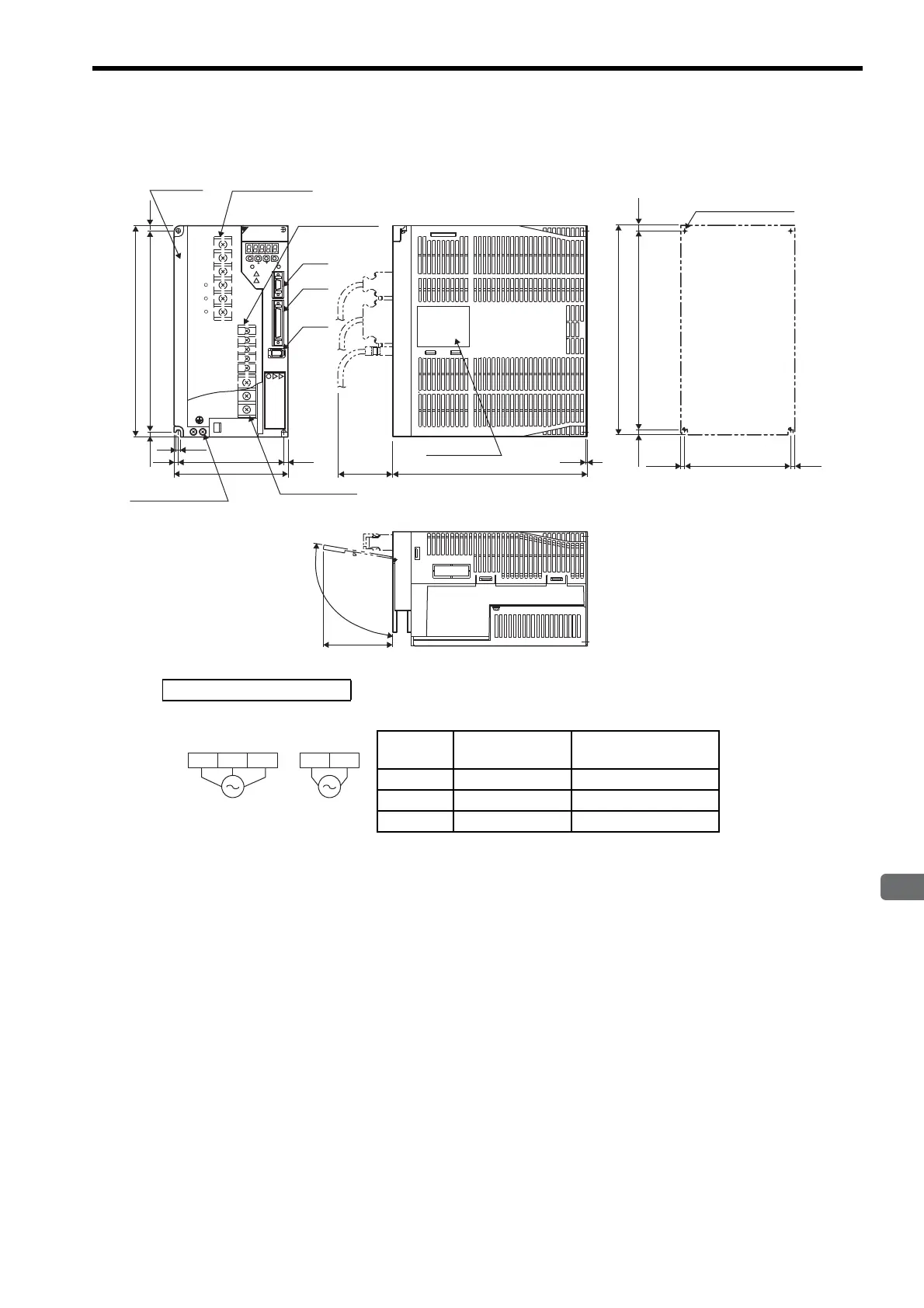
4.7.6 Three-phase 200 V: 5.0 kW (50ADA)
Ve r.
SGDM-50ADA
(83)
CN2
CN3
4-pin terminal
M4 screw
250
Heat sink 6-pin terminal
M5 screw
(75)
230
1.6
125
6
238.5
5.7
(5.5)
(5)
(5)
3-pin terminal
M5 screw
135
CN1
(100°)
YASKAWA SERVOPACK
L1
L2
L2C
B1
B2
B3
U
V
W
L1C
L3
1
+
2
+
-
250
238.5±0.5
125±0.5
(5.5)
(5)
(5)
6
MODE/SET
CHARGE POWER
DATA/
Nameplate
(Mounting pitch)
(Mounting pitch)
4×M5 screw taps
Mounting Hole Diagram
Units: mm
Approx. mass: 5.5 kg
Ground terminal
M5 screw
External Terminal Connector
SERVOPACK Connector
Connector
Symbol
SERVOPACK
Connector Model
Manufacturer
CN1 10250-52A2JL Sumitomo 3M Co., Ltd.
CN2 53460-0611 Molex Japan Co., Ltd.
CN3 10214-52A2JL Sumitomo 3M Co., Ltd.
L1C L2CL2 L3L1
200 VAC
50/60 Hz
Three-phase
200 VAC
50/60 Hz
Single-phase
Main circuit
power supply
Control power
supply

 Loading...


