6.4 Others
6-25
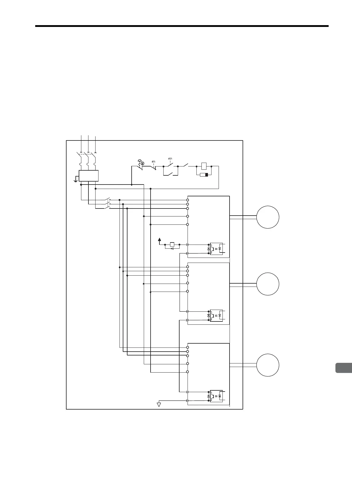
6.4.5 Using More Than One SERVOPACK
The following diagram is an example of the wiring when more than one SERVOPACK is used.
Connect the alarm output (ALM) terminals for the three SERVOPACKs in series to enable alarm detection relay
1RY to operate.
When the alarm occurs, the ALM output signal transistor is turned OFF.
Multiple servos can share a single molded-case circuit breaker (QF) or noise filter. Always select a QF or noise
filter that has enough capacity for the total power capacity (load conditions) of those servos. For details, refer to
2.5.2 Molded-case Circuit Breaker and Fuse Capacity.
RS T
QF
1KM
1KM
1RY
SA
1KM
1RY
+24V
L1
L2
L3
L1C
CN1
31 ALM+
32 ALM
-
0V
M
L2C
M
M
Power supply
Noise
filter
Power
ON
Power
OFF
SERVOPACK
Servomotor
Servomotor
Servomotor
Note: Wire the system, so that the phase-S power supply will be the ground phase.
L1
L2
L3
L1C
CN1
31 ALM+
32 ALM
-
L2C
SERVOPACK
L1
L2
L3
L1C
CN1
31 ALM+
32 ALM
-
L2C
SERVOPACK

 Loading...


