5 Specifications and Dimensional Drawings of Cables and Peripheral Devices
5.2.2 SGMAH and SGMPH Servomotor Connectors for Standard Environments
5-10
(b) Connector Pin Arrangement
(5) 1.5 kW SGMPH Servomotors Without Brakes
(a) Connector Type: JZSP-CMM9-3
(b) Connector Pin Arrangement
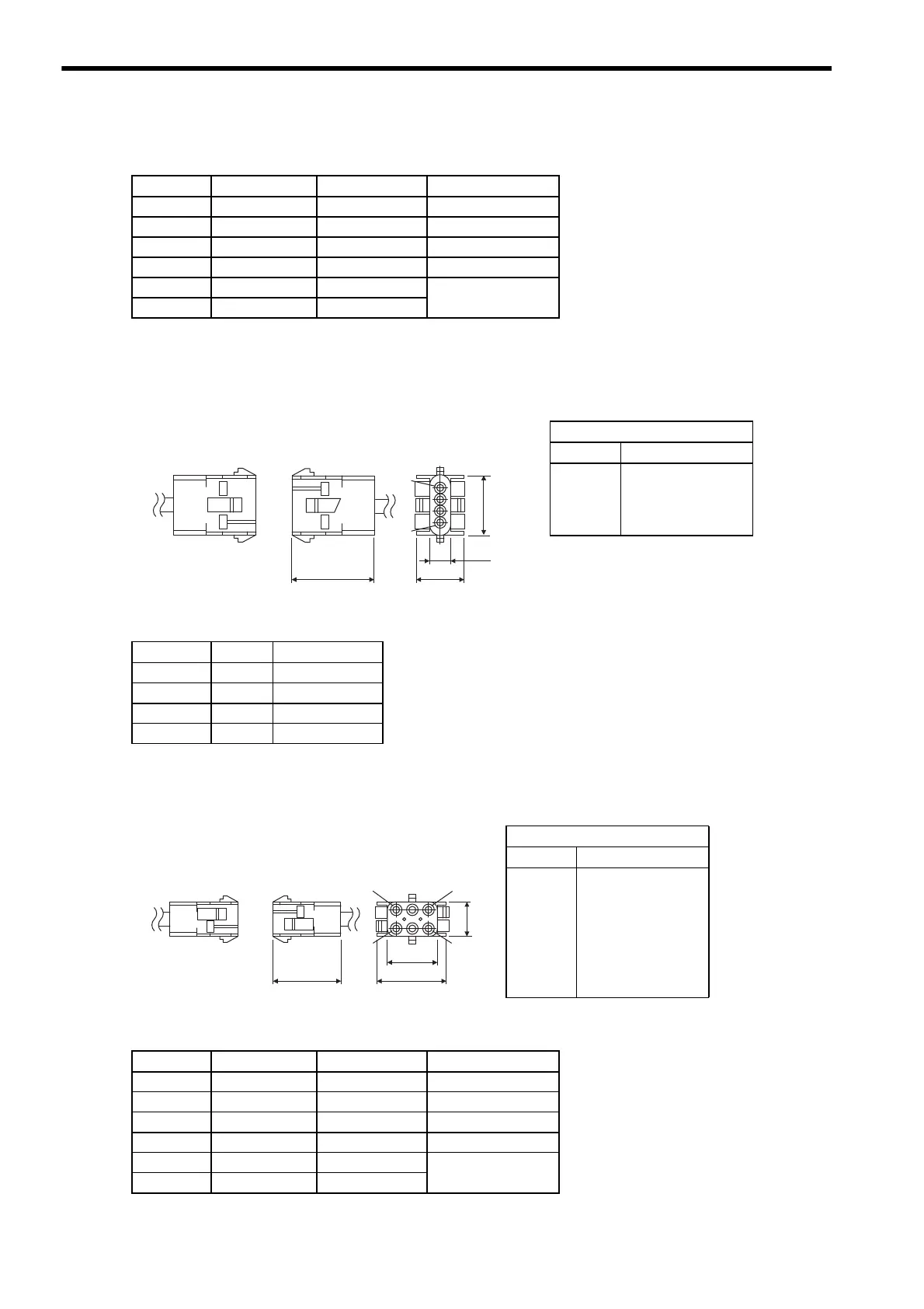
(6) 1.5 kW SGMPH Servomotors With Brakes
(a) Connector Type: JZSP-CMM9-4
(b) Connector Pin Arrangement
Pin No. Signal Lead Color Remarks
1Phase U Red −
2 Phase V White −
3 Phase W Blue −
4 FG Green/Yellow −
5 Brake terminal Black
No polarity
6 Brake terminal Black
Type
Cap 350780-1
Socket
350536-6 or
350550-6
(No. 1 to 4)
Soldered type
Pin No. Signal Lead Color
1Phase U Red
2 Phase V White
3 Phase W Blue
4 FG Green/Yellow
14.7
27.4
7.6
4
1
27.7
Connector on
servomotor
Servomotor main
circuit connector
Units: mm
Type
Cap 350781-1
Socket
350536-6 or
350550-6
(No. 1 to 4)
350570-3 or
350689-3
(No. 5 and 6)
Soldered type
Pin No. Signal Lead Color Remarks
1Phase U Red −
2 Phase V White −
3 Phase W Blue −
4 FG Green/Yellow −
5 Brake terminal Black
No polarity
6 Brake terminal Black
28.4
20.3
6
3
1
4
27.4
14
Connector on
servomotor
Units: mm
Servomotor main
circuit connector

 Loading...


