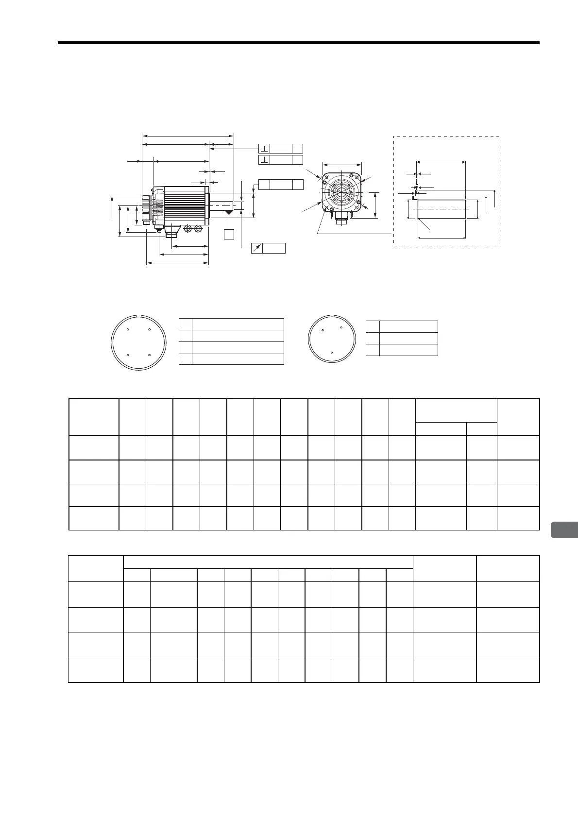
3.15 Dimensional Drawings of SGMGH Servomotors (1500 min
-1
)
3-83
3
Servomotor Specifications and Dimensional Drawings
(2) 5.5kW to 15kW
Models with oil seals are of the same configuration.
LC
4-φ13.5 Mounting holes
φLA
φLH
IE
Shaft End
LR
110
R1
φS
φS1
φLJ2
φLJ1
LE
LF1
LF2
Note: For the specifications of the other shaft ends, refer to
3.20 Shaft End Specifications for SGMGH, SGMSH
and SGMDH Servomotors.
* For 1AA to 1EA only
*
KB1
KB2
KB3
L
φS
100
88
φLB
٧ A
A
LR
LE
LG
LM
LT
LL
KL1
KL3
A
A0.06
0.04
φ0.04
0.04
A
A Phase U
Phase V
Phase W
FG (Frame ground)
B
C
D
D
CB
Cable Specifications for Servomotor
Connectors
A
A Brake terminal
Brake terminal
−
B
C
C
B
Cable Specifications for Brake
Connectors
Units: mm
Model
SGMGH-
L LL LM LR LT KB1 KB2 KB3 IE KL1 KL3
Shaft-end
Dimensions
Approx.
Mass
kg
SS1
55AA2
424 311 263 113 48 174 289 231 123 150 123 45 35
75AA2
498 385 337 113 48 248 363 305 123 150 123 45 45.5
1AAA2
499 383 340 116 43 258 362 315 142 168 142 45 65
1EAA2
635 519 471 116 48 343 497 415 150 168 142 65 100
Units: mm
Model
SGMGH-
Flange Face Dimensions
Allowable
Radial Load N
Allowable
Thrust Load N
LA LB LC LE LF1 LF2 LG LH LJ1 LJ2
55AA2
200 180 3.2 3 0.5 18 230 76 62 1764 588
75AA2
200 180 3.2 3 0.5 18 230 76 62 1764 588
1AAA2
235 220 4 4 − 18 270 62 − 1764 588
1EAA2
235 220 4 4 − 20 270 85 − 4998 2156

 Loading...


