5 Specifications and Dimensional Drawings of Cables and Peripheral Devices
5.2.4 SGMGH Servomotor (1500 min
-1
) Connectors for Standard Environments
5-14
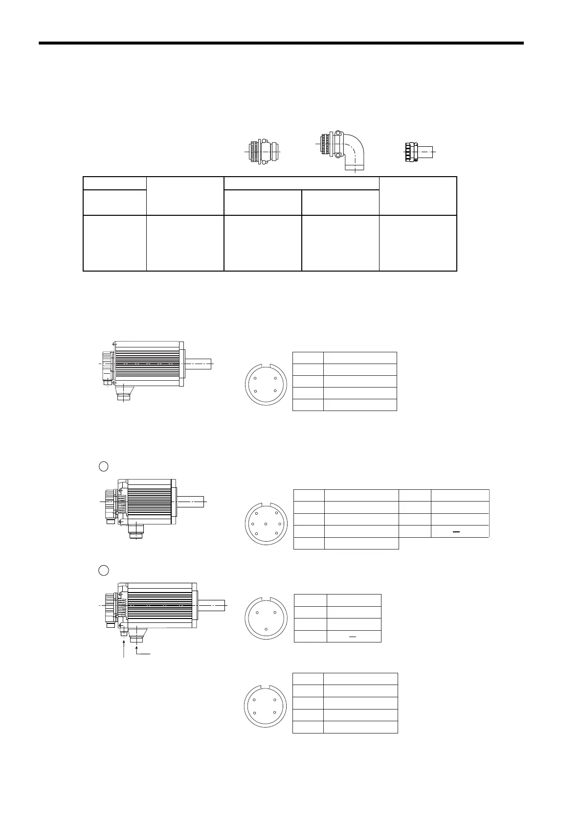
(b) Brake Power Supply Connectors
5.5 to 15.0 kW Servomotors
(3) SGMGH Servomotors (1500 min
-1
) Main Circuit Connector Pin Arrangement
(a) Without Holding Brakes
(b) With Holding Brakes
Capacity (kW)
Connector on
Servomotor
Plug
Cable Clamp
Three-phase
200 V
Straight L-shaped
5.5
7.5
11.0
15.0
MS3102A10SL-3P MS3106A10SL-3S
Use the connector
conforming to
protective structure
IP67/European
safety standard.
MS3057-4A
0.45 to 15.0 kW
Servomotor-end
connector
Servomotor Connector Pin Arrangement
A
B
C
D
Phase U
Phase V
Phase W
FG (Frame Ground)
D
BC
A
Pin No. Signal
1 0.45 to 4.4 kW
2 5.5 to 15.0 kW
Servomotor-end
connector
Servomotor-end connector
Brake-end connector
Brake Connector Pin Arrangement
B
C
A
Servomotor Connector Pin Arrangement
Servomotor Connector Pin Arrangement
D
B
G
C
AF
E
A
B
C
D
Phase U
Phase V
Phase W
FG (Frame Ground)
Pin No. Signal
E *
F *
G
Brake terminal
Brake terminal
Pin No. Signal
A
B
C
D
Phase U
Phase V
Phase W
FG (Frame Ground)
D
BC
A
Pin No. Signal
A *
B *
C
Brake terminal
Brake terminal
Pin No. Signal
* No polarity
* No polarity

 Loading...


