5 Specifications and Dimensional Drawings of Cables and Peripheral Devices
5.2.8 SGMGH Servomotor (1500 min
-1
) Connectors Conforming to IP67 and European Safety Standards
5-22
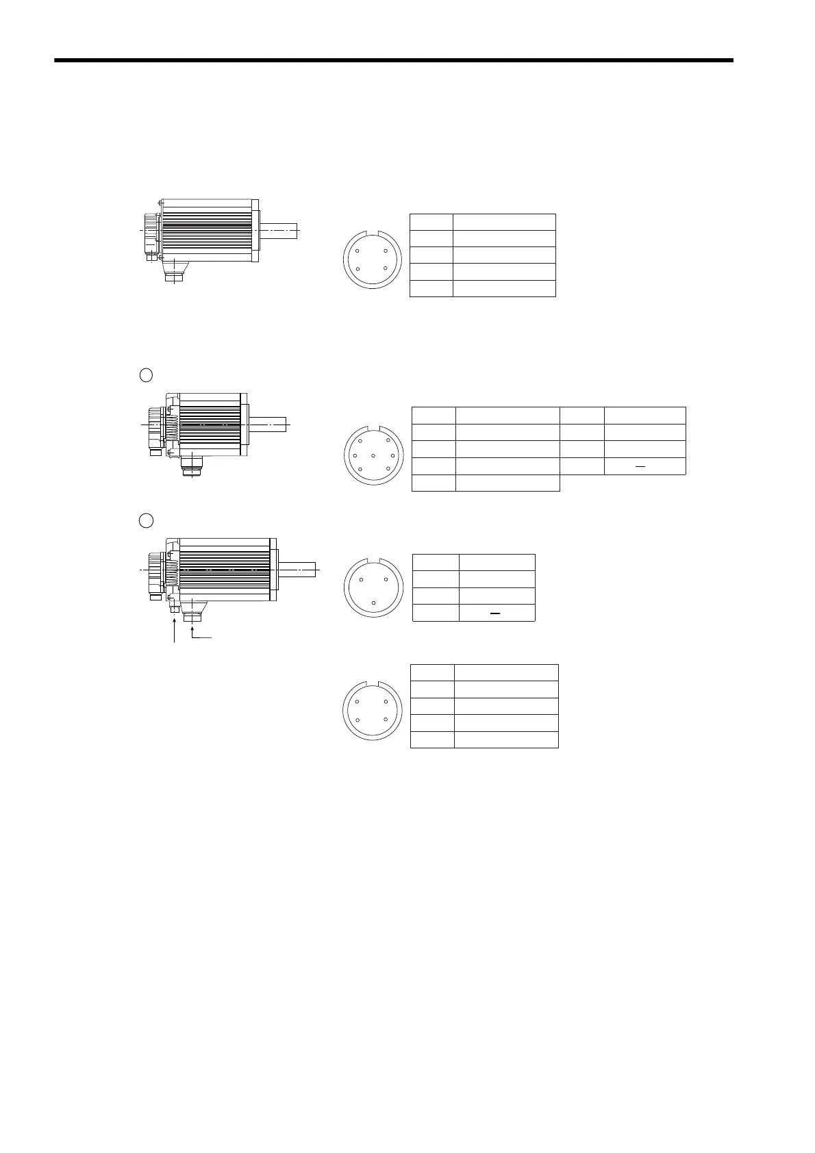
(5) Servomotor Main Circuit Connector Pin Arrangement
(a) Servomotors Without Holding Brakes
(b) Servomotors With Holding Brakes
0.45 to 15.0 kW
Servomotor-end
connector
Servomotor Connector Pin Arrangement
A
B
C
D
Phase U
Phase V
Phase W
FG (Frame Ground)
D
BC
A
Pin No. Signal
1 0.45 to 4.4 kW
2 5.5 to 15.0 kW
Servomotor-end
connector
Servomotor-end connector
Brake-end connector
Brake Connector Pin Arrangement
B
C
A
Servomotor Connector Pin Arrangement
Servomotor Connector Pin Arrangement
D
B
G
C
AF
E
A
B
C
D
Phase U
Phase V
Phase W
FG (Frame Ground)
Pin No. Signal
E *
F *
G
Brake terminal
Brake terminal
Pin No. Signal
A
B
C
D
Phase U
Phase V
Phase W
FG (Frame Ground)
D
BC
A
Pin No. Signal
A *
B *
C
Brake terminal
Brake terminal
Pin No. Signal
* No polarity
* No polarity
 Loading...


