5.2 Servomotor Main Circuit Wire Size and Connectors
5-25
5
Specifications and Dimensional Drawings of Cables and Peripheral Devices
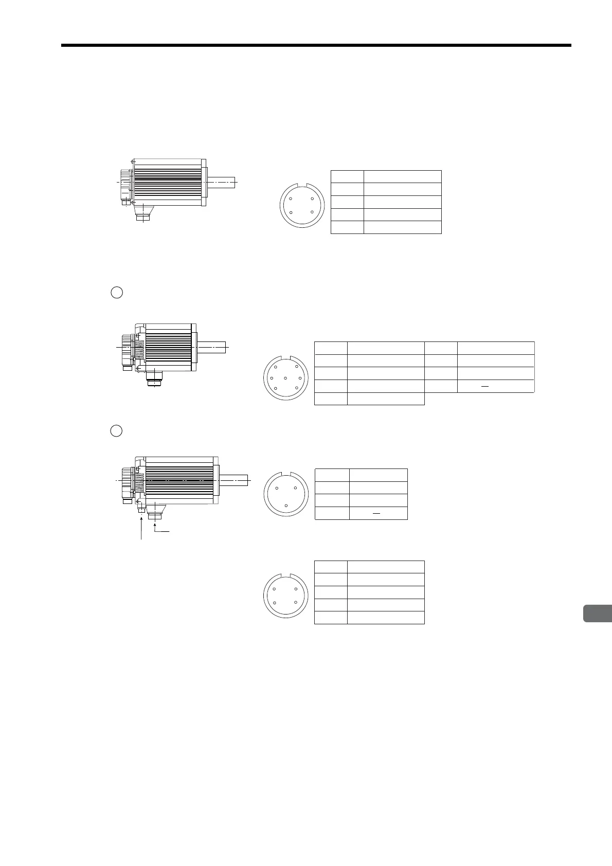
(4) Servomotor Main Circuit Connector Pin Arrangement
(a) Servomotors Without Holding Brakes
(b) Servomotors With Holding Brakes
0.3 to 5.5 kW
Servomotor Connector Pin Arrangement
A
B
C
D
Phase U
Phase V
Phase W
FG (Frame Ground)
D
BC
A
Pin No. Signal
Servomotor-end
connector
1 0.3 to 3.0 kW
2 4.0 kW and 5.5 kW
Servomotor-end
connector
Servomotor-end connector
Brake-end connector
Brake Connector Pin Arrangement
B
C
A
Servomotor Connector Pin Arrangement
Servomotor Connector Pin Arrangement
D
B
G
C
AF
E
A
B
C
D
Phase U
Phase V
Phase W
FG (Frame Ground)
Pin No. Signal
E *
F *
G
Brake terminal
Brake terminal
Pin No. Signal
A
B
C
D
Phase U
Phase V
Phase W
FG (Frame Ground)
D
BC
A
Pin No. Signal
A *
B *
C
Brake terminal
Brake terminal
Pin No. Signal
* No polarity
* No polarity
 Loading...


