6.1 Wiring Main Circuit
6-3
* If using the main circuit power supply and the control power supply with DC power supply input, refer to 6.1.3
Typical Main Circuit Wiring Examples (3) DC Power Supply Input for more information on wiring.
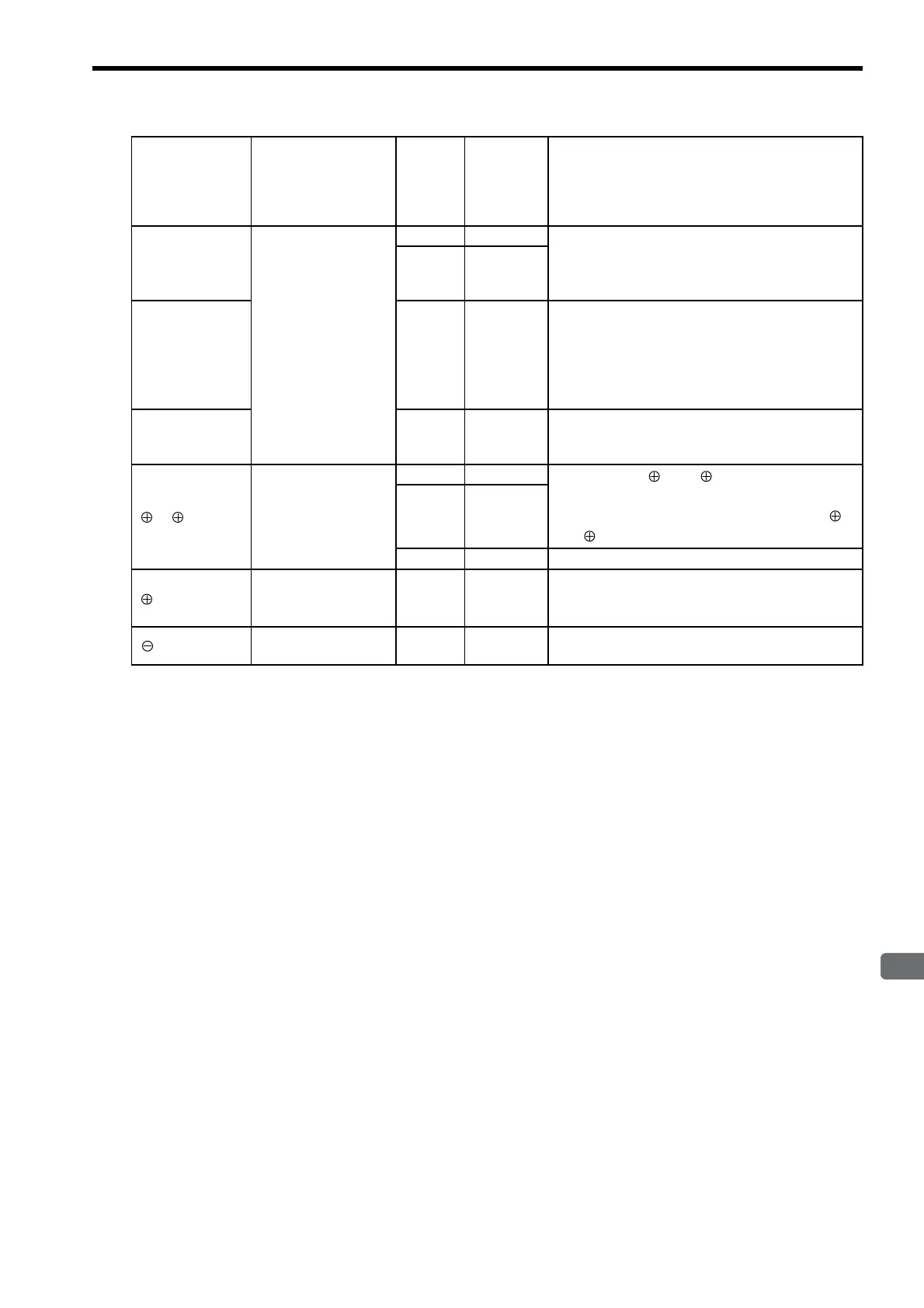
B1
,
B2
External
regenerative
resistor connection
terminal
100 0.03 to 0.2
Normally not connected.
Connect an external regenerative resistor (provided
by customer) between B1 and B2 if the regenerative
capacity is insufficient.
200 0.03 to 0.4
B1
,
B2
,
B3
200 0.5 to 5.0
Normally short B2 and B3 (for an internal regenera-
tive resistor).
Remove the wire between B2 and B3 and connect an
external regenerative resistor (provided by customer)
between B1 and B2 if the capacity of the internal
regenerative resistor is insufficient.
B1
,
B2
200 6.0 to 15.0
Connect an external regenerative resistor (provided
by customer) between B1 and B2. Refer to 6.5 Con-
necting Regenerative Resistors for details.
1
,
2
DC reactor for
harmonic
suppression
terminal
100 0.03 to 0.2
Normally short 1 and 2 .
If a countermeasure against power supply harmonic
waves is needed, connect a DC reactor between 1
and 2.
200 0.03 to 5.0
200 6.0 or more
These terminals do not exist.
Main circuit plus
terminal
200 6.0 or more
Normally not connected.
Note: This terminal is on the SERVOPACK with a
capacity of 6.0 kW or higher only.
Main circuit minus
terminal
−−
Normally not connected.
Terminal Symbol Name
Main
Circuit
Voltage
(V)
Maximum
Applicable
Servomotor
Capacity
(kW)
Functions

 Loading...


