6.3 Examples of I/O Signal Connections
6-17
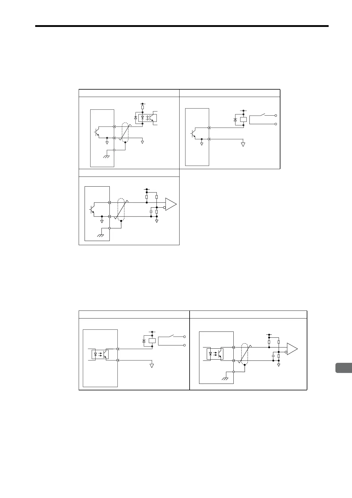
(b) Open-collector Output Circuit
CN1 connector terminals 37 to 39: Alarm code output are explained below.
Alarm code signals (ALO1, ALO2, ALO3) are output from open-collector transistor output circuits. Connect
an open-collector output circuit through a photocoupler, relay circuit, or line receiver circuit.
Note: The maximum allowable voltage and current capacities for open-collector output circuits are as
follows:
• Voltage: 30 VDC
• Current: 20 mA DC
(c) Photocoupler Output Circuit
Photocoupler output circuits are used for servo alarm (ALM), servo ready (/S-RDY), and other sequence out-
put signal circuits. Connect a photocoupler output circuit through a relay circuit or line receiver circuit.
Note: The maximum allowable voltage and current capacities for photocoupler output circuits are as
follows:
• Voltage: 30 VDC
• Current: 50 mA DC
Photocoupler Circuit Example Relay Circuit Example
Line Receiver Circuit Example
Relay Circuit Example Line Receiver Circuit Example
0V
0V
SERVOPACK
5 to 12 VDC
Photocoupler
0V
Relay
5 to 24 VDC
SERVOPACK
0V
Relay
5 to 24 VDC
SERVOPACK

 Loading...


