6.5 Connecting Regenerative Resistors
6-33
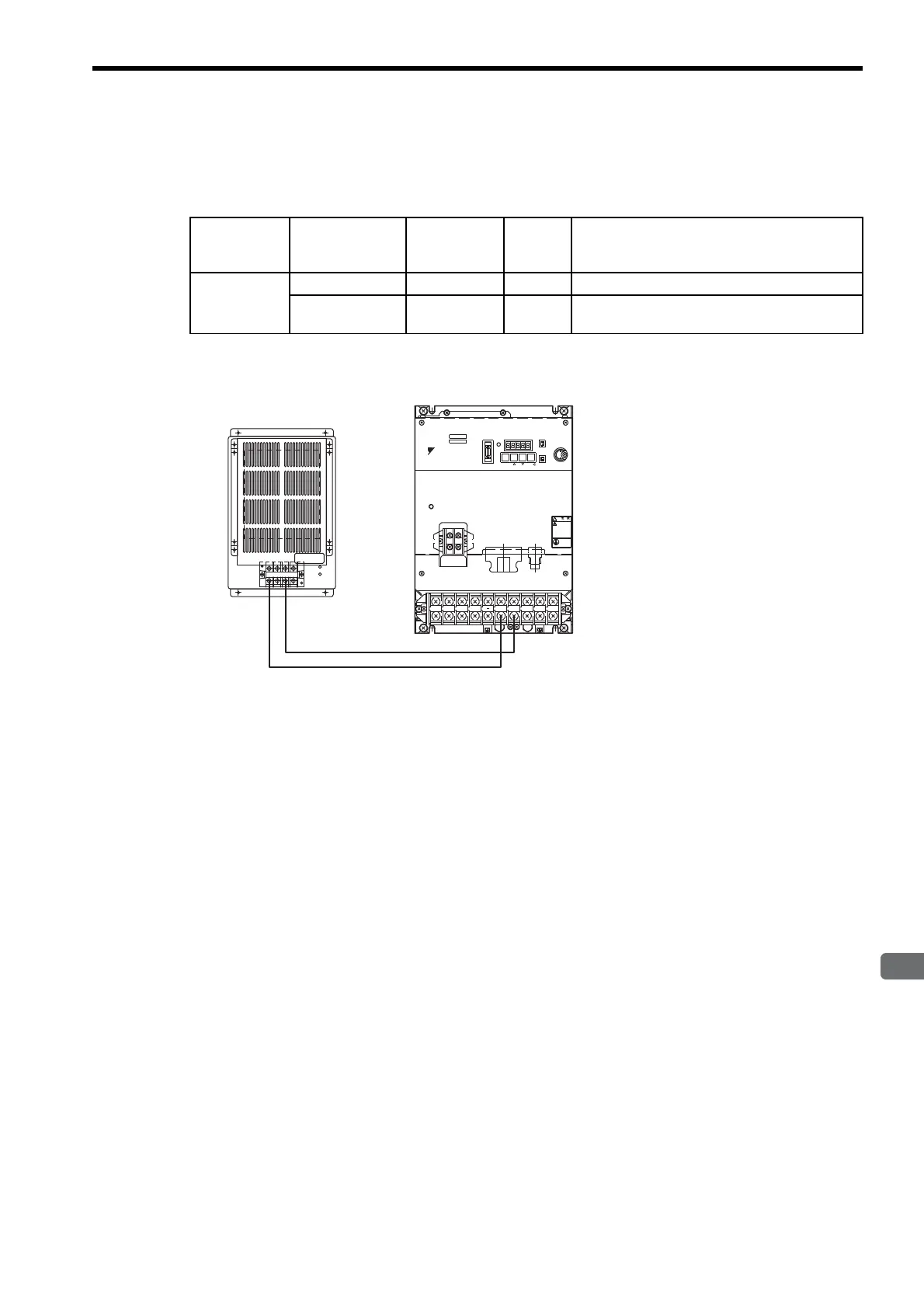
(c) SERVOPACK’s with Capacities of 6.0 kW or More
No built-in regenerative resistor is provided, so the external regenerative resistor is required. The special
regenerative resistor units are as follow:
The following diagram shows the connection method between the SERVOPACK and the regenerative resis-
tor unit.
Note: Connect a regenerative resistor unit between B1 and B2 terminals. The regenerative resistor unit is
provided by the customer.
Main Circuit
Power Supply
Applicable
SERVOPACK
Model SGDM-
Applicable
Regenerative
Resistor Unit
Resis-
tance
(Ω)
Specifications
Three-phase
200 V
60ADA JUSP-RA04
6.25
25
Ω(
220 W
)×
4 (parallel connection)
75ADA to -
1EADA
JUSP-RA05
3.13
25
Ω(
220 W
)×
8 (parallel connection)
L1 L2 L3
UB2B1+ VW
WARNING
MODE/SET D ATA/
Ve r.
POWER
BATTERY
CHARGE
SGDM-
SERVOPARK 200V
YASKAWA
Regenerative Resistor Unit
JUSP-RA
SERVOPACK

 Loading...


