EasyManuals Logo

YASKAWA Sigma II Series User Manual

YASKAWA Sigma II Series
578 pages
To Next Page IconTo Next Page
To Previous Page IconTo Previous Page
Page #446 background imageLoading...
Page #446 background image
8.7 Operating Using Torque Control
8-65
8
Operation
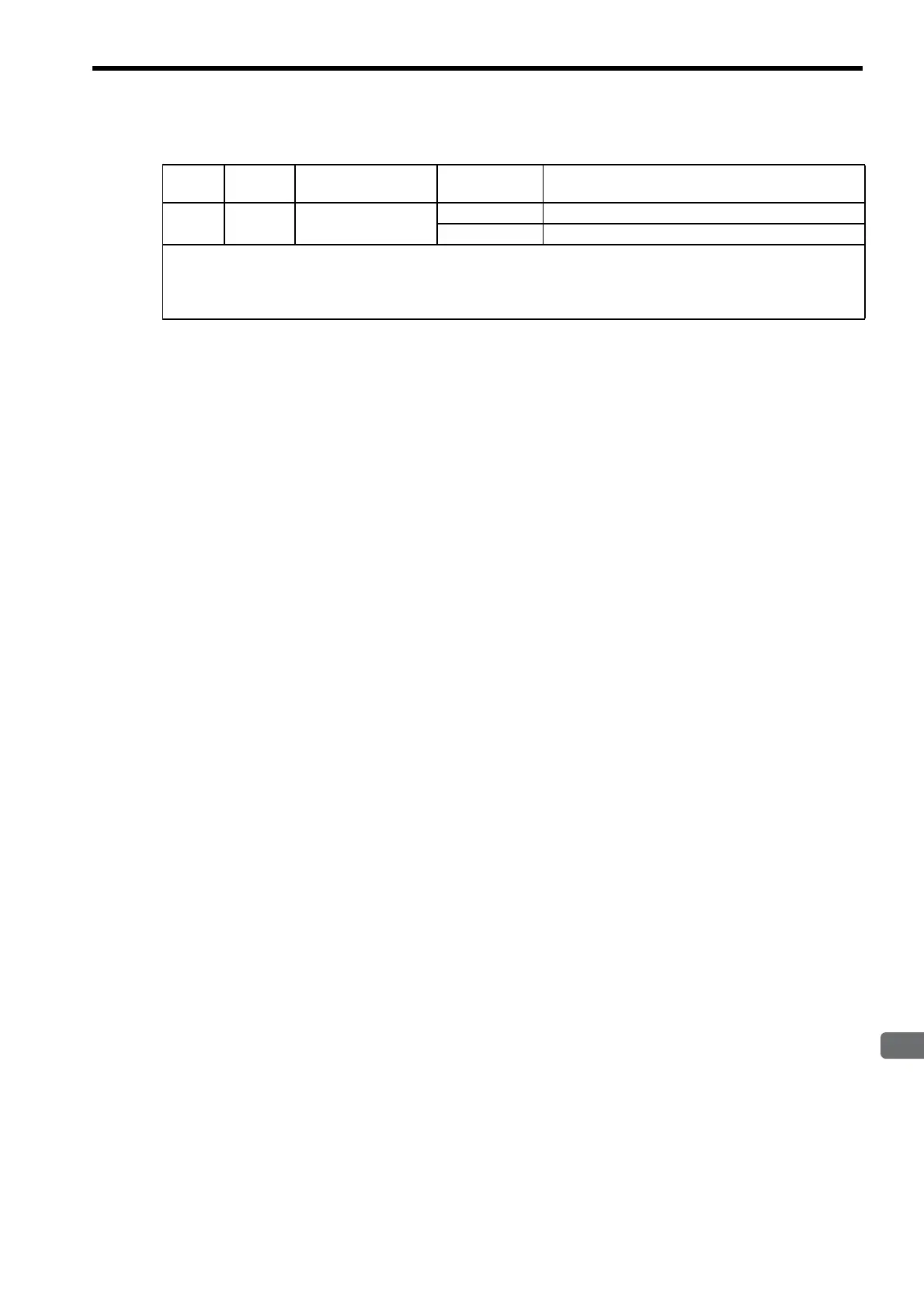
(4) Signals Output during Servomotor Speed Limit
Type Signal
Name
Connector
Pin Number
Setting Meaning
Output /VLT Must be allocated
CN1-
ON (low level) Servomotor speed limit being applied.
OFF (high level) Servomotor speed limit not being applied.
This signal is output when the servomotor speed reaches the speed limit value set in Pn407 or set by the analog voltage ref-
erence.
For use, this output signal must be allocated with parameter Pn50F. For details, refer to 7.3.3 Output Circuit Signal Alloca-
tion.

Table of Contents

Questions and Answers:

Question and Answer IconNeed help?

Do you have a question about the YASKAWA Sigma II Series and is the answer not in the manual?

YASKAWA Sigma II Series Specifications

General IconGeneral
BrandYASKAWA
ModelSigma II Series
CategoryController
LanguageEnglish

Related product manuals