10 Upgraded Versions
10.3.1 SGMCS Direct-drive Motor Supporting Function
10-6
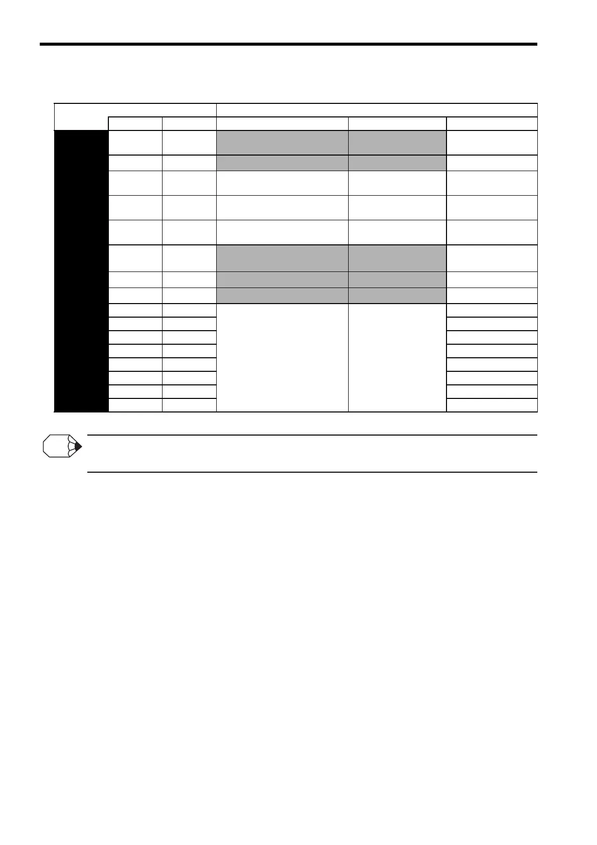
Also, the analog monitor output units are changed as shown in the shaded areas in the following table.
* When using speed control or torque control, the position error monitor signal is variable.
The maximum output voltage of the analog monitor is ±8V. If the input voltage is outside of this range, it will be output as
±8V.
Parameter Description
Monitor 1 Monitor 2 Monitor Signal Measurement Gain Remarks
Pn003
n.0 n.0
Motor speed
1 V / 100 min
-1
Monitor 2:
Factory setting
n.1 n.1
Speed reference
1 V / 100 min
-1
n.2 n.2 Internal torque reference
1 V / 100%
Rated Torque
Monitor 1:
Factory setting
n.3 n.3
Position error
∗
0.05 V / 1
Reference Units
n.4 n.4
Position error
∗
0.05 V / 100
Reference Units
n.5 n.5
Reference pulse frequency
(Converted to min
-1
)
1 V / 100 min
-1
n.6 n.6 Motor speed × 4
1 V / 25 min
-1
n.7 n.7 Motor speed × 8
1 V / 12.5 min
-1
n.8 n.8
Reserved (Do not use.)
−
n.9 n.9
n.A n.A
n.B n.B
n.C n.C
n.D n.D
n.E n.E
n.F n.F

 Loading...


