10 Upgraded Versions
10.3.3 Reference Pulse Input Multiplication Switching Function
10-10
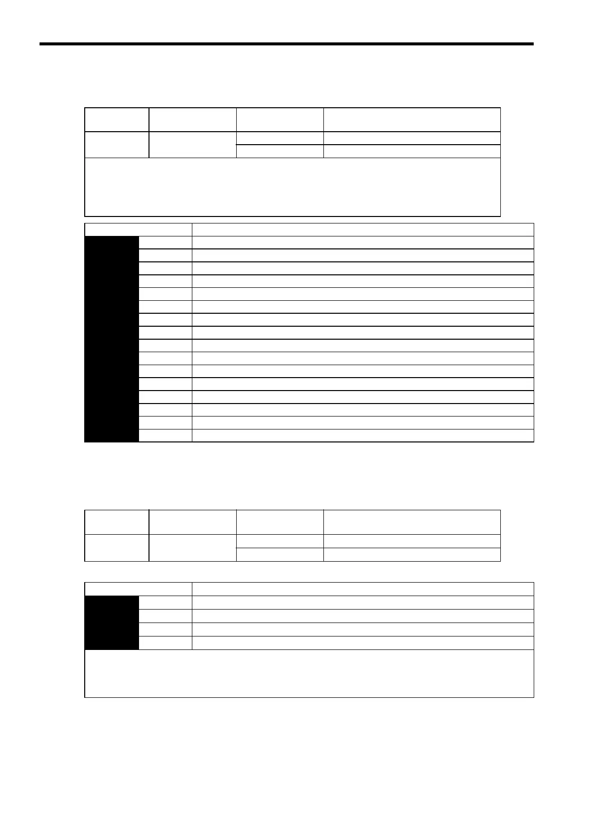
(3) Input Signal Selection
Note: After changing the setting, turn OFF the power and ON again to enable the new setting.
(4) Output Signal Selection
The /PSELA signal is the output signal that indicates if switching for reference pulse input multiplication is
enabled by /PSEL signal or not.
The /PSELA signal can’t be used with the factory setting. Allocate the /PSELA output signal.
Note: After changing the setting, turn OFF the power and ON again to enable the new setting.
Signal Name
Connector Pin
Number
Setting Meaning
/PSEL
Signal allocation not
required
ON (low level) Enabled when the /PSEL signal turns ON.
OFF (high level) Disabled when the /PSEL signal turns OFF.
The /PSEL signal is the input signal that switches the multiplication factor of the reference pulse input to the value
set in Pn217.
This signal must be allocated in parameter Pn513.0 as shown in the following table. Refer to 7.3.2 Input Circuit
Signal Allocation for more information on how to allocate input signals. After setting Pn217, turn OFF the power
supplies for the main circuit and the control and then turn ON again.
Parameter Description
Pn513 n.0 Inputs from the SI0 (CN1-40) input terminal.
n.1 Inputs from the SI1 (CN1-41) input terminal.
n.2 Inputs from the SI2 (CN1-42) input terminal.
n.3 Inputs from the SI3 (CN1-43) input terminal.
n.4 Inputs from the SI4 (CN1-44) input terminal.
n.5 Inputs from the SI5 (CN1-45) input terminal.
n.6 Inputs from the SI6 (CN1-46) input terminal.
n.7 Sets the signal ON.
n.8 Sets the signal OFF. (Factory setting)
n.9 Inputs the reverse signal from the SI0 (CN1-40) input terminal.
n.A Inputs the reverse signal from the SI1 (CN1-41) input terminal.
n.B Inputs the reverse signal from the SI2 (CN1-42) input terminal.
n.C Inputs the reverse signal from the SI3 (CN1-43) input terminal.
n.D Inputs the reverse signal from the SI4 (CN1-44) input terminal.
n.E Inputs the reverse signal from the SI5 (CN1-45) input terminal.
n.F Inputs the reverse signal from the SI6 (CN1-46) input terminal.
Signal Name
Connector Pin
Number
Setting Meaning
/PSELA
Signal allocation not
required
ON (low level) Enabled when the /PSEL signal turns ON.
OFF (high level) Disabled when the /PSEL signal turns OFF.
Parameter Meaning
Pn510 n.0 Disabled
n.1 Outputs the /PSELA signal from the CN1-25, 26 output terminal.
n.2 Outputs the /PSELA signal from the CN1-27, 28 output terminal
n.3 Outputs the /PSELA signal from the CN1-29, 30 output terminal.
For the factory settings, the pins CN1-25 to CN1-30 are allocated for other output signals. If multiple signals are allocated
to the same output terminal, signals are output with OR logic. To enable only the /PSELA output signal, allocate the other
signals to other output terminals or disable the other signals.
Refer to 7.3.3 Output Circuit Signal Allocation for the allocation of output signals.
 Loading...


