11.1 Troubleshooting
11-7
11
Inspection, Maintenance, and Troubleshooting
A.32
Regenerative
Overload
(Detected only
when the power
to the main circuit
is ON.)
Occurred when the
control power sup-
ply was turned ON.
A SERVOPACK board fault occurred. Replace the SERVOPACK.
Occurred when the
main circuit power
supply was turned
ON.
The power supply voltage is 270 V or more. Correct the input voltage.
Occurred during
normal operation
(large increase of
regenerative resistor
temperature).
The regenerative energy is excessive.
Select a proper regenerative resistance capacity,
or reconsider the load and operation conditions.
The regenerating state continued.
Occurred during
normal operation
(small increase of
regenerative resistor
temperature).
The setting of parameter Pn600 is smaller than the
external regenerative resistor’s capacity.
Correct the set value of parameter Pn600.
A SERVOPACK fault occurred. Replace the SERVOPACK.
Occurred at servo-
motor deceleration.
The regenerative energy is excessive.
Select a proper regenerative resistance capacity,
or reconsider the load and operation conditions.
A.33
Main Circuit
Wiring Error
(Detected only
when the power
to the main circuit
is ON.)
Occurred when the
control power sup-
ply was turned ON.
A SERVOPACK board fault occurred. Replace the SERVOPACK.
Occurred when the
main circuit power
supply was turned
ON.
In the DC power input mode, AC power is supplied
through L1 and L2 or L1, L2, and L3.
For AC power input, Pn001.2=0.
For DC power input, Pn001.2=1.
In the AC power input mode, DC power is supplied
through 1 and terminals.
Pn600 is set to 0 if the regenerative resistance is dis-
connected.
Set Pn600 to 0.
A.40
Overvoltage
(Detected when
the
SERVOPACK’s
main circuit DC
voltage is 240 V
(100 V class)/420
V (200 V class)
or more.)
(Detected only
when the power
to the main circuit
is ON.)
Occurred when the
control power sup-
ply was turned ON.
A SERVOPACK board fault occurred. Replace the SERVOPACK.
Occurred when the
main circuit power
supply was turned
ON.
The AC power voltage is too high.
The AC power voltage must be within the speci-
fied range.
A SERVOPACK fault occurred. Replace the SERVOPACK.
Occurred during
normal operation.
Check the AC power voltage (check if there is no
excessive voltage change.)
The AC power voltage must be within the speci-
fied range.
The motor speed is high and load moment of inertia
is excessive, resulting in insufficient regenerative
capacity.
Reconsider the load and operation conditions.
Check the load moment of inertia and minus load
specifications.
A SERVOPACK fault occurred. Replace the SERVOPACK.
Occurred at servo-
motor deceleration.
The motor speed is high, and the load moment of
inertia is excessive.
Reconsider the load and operation conditions.
A.41
Undervoltage
(Detected when
the
SERVOPACK’s
main circuit DC
voltage is 85 V
(100 V class)/170
V (200 V class)
or less.)
(Detected only
when the power
to the main circuit
is ON.)
Occurred when the
control power sup-
ply was turned ON.
A SERVOPACK board fault occurred. Replace the SERVOPACK.
Occurred when the
main circuit power
supply was turned
ON.
The AC power supply voltage is low.
The AC power supply voltage must be within the
specified range.
The fuse of the SERVOPACK is blown out. Replace the SERVOPACK.
The inrush current limit resistor is disconnected,
resulting in an abnormal power supply voltage or in
an overload of the inrush current limit resistor.
Replace the SERVOPACK. Check the power
supply voltage, and reduce the number of times
that the main circuit is turned ON or OFF.)
A SERVOPACK fault occurred. Replace the SERVOPACK.
Occurred during
normal operation.
The AC power supply voltage was lowered, and
large voltage drop occurred.
The AC power supply voltage must be within the
specified range.
A temporary power failure occurred.
Clear and reset the alarm, and restart the opera-
tion.
The servomotor main circuit cable is short-cir-
cuited.
Repair or replace the servomotor main circuit
cable.
The servomotor is short-circuited. Replace the servomotor.
A SERVOPACK fault occurred. Replace the SERVOPACK.
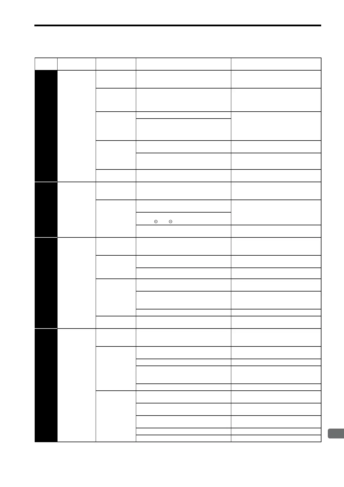
Table 11.3 Alarm Display and Troubleshooting (Cont’d)
Alarm
Display
Alarm Name
Situation at Alarm
Occurrence
Cause Corrective Actions

 Loading...


