• If the motor vibrates, increase C4-02
• If the motor response is sluggish (and possibly stalls), decrease C4-02.
Note: Auto-Tuning significantly improves drive performance at low speeds.
n
C4-03: Torque Compensation at Forward Start (OLV only)
Sets the amount of torque at start (when rotating forward) as a percentage of the motor rated torque. This parameter may improve the motor performance
during start. This feature functions only when starting a motor in the forward direction. Torque reference and motor flux can be ramped up quickly to
improve speed response during start. A setting of 0.0 disables this feature.
No. Parameter Name Setting Range Default
C4-03 Torque Compensation at Forward Start 0.0 to 200.0 0.0%
n
C4-04: Torque Compensation at Reverse Start (V/f Control)
This parameter may improve the motor performance during start. This feature functions only when starting a motor in the reverse direction. Torque
reference and motor flux can be ramped up quickly to improve speed response during start. A setting of 0.0 disables this feature.
No. Parameter Name Setting Range Default
C4-04 Torque Compensation at Reverse Start -200.0 to 0.0 0.0%
n
C4-05: Torque Compensation Time Constant (OLV only)
This parameter is the time delay that will be applied to the torque compensation parameters C4-03 and C4-04.
No. Parameter Name Setting Range Default
C4-05 Torque Compensation Time Constant 0 to 200 10 ms
n
C4-06: Torque Compensation Primary Delay Time 2 (V/f Control)
Increase settings when acceleration is complete, or if an overvoltage fault or error occurs with sudden changes in the load. Adjustment is not normally
required.
No. Parameter Name Setting Range Default
C4-06 Torque Compensation Primary Delay Time 2 0 to 10000 150 ms
Note: If C4-06 is set to a relatively large value, be sure to also increase the setting in n2-03 (AFR Time Constant 2) proportionally.
u
C5: ASR
The automatic speed regulator (ASR) provides optimum performance during changes in motor speed or load by using speed feedback.
Note: C5 parameters will appear only when using V/f Conrol (A1-02 = 0) and the Pulse Train function is set to allow Simple PG in V/f (H6-01 = 3).
No. Parameter Name Setting Range Default Page
A1-02 Control Method Selection
0: V/f Control
2: Open Loop Vector
5: PM Open Loop Vector
0 −
H6-01
Terminal RP Pulse Train Input Function
Selection
Selects the function of pulse train terminal RP.
0: Frequency reference
1: PID feedback value
2: PID setpoint value
3: Motor speed when using Simple PG V/f Control (can be set only when using motor
1 in V/f Control)
0 −
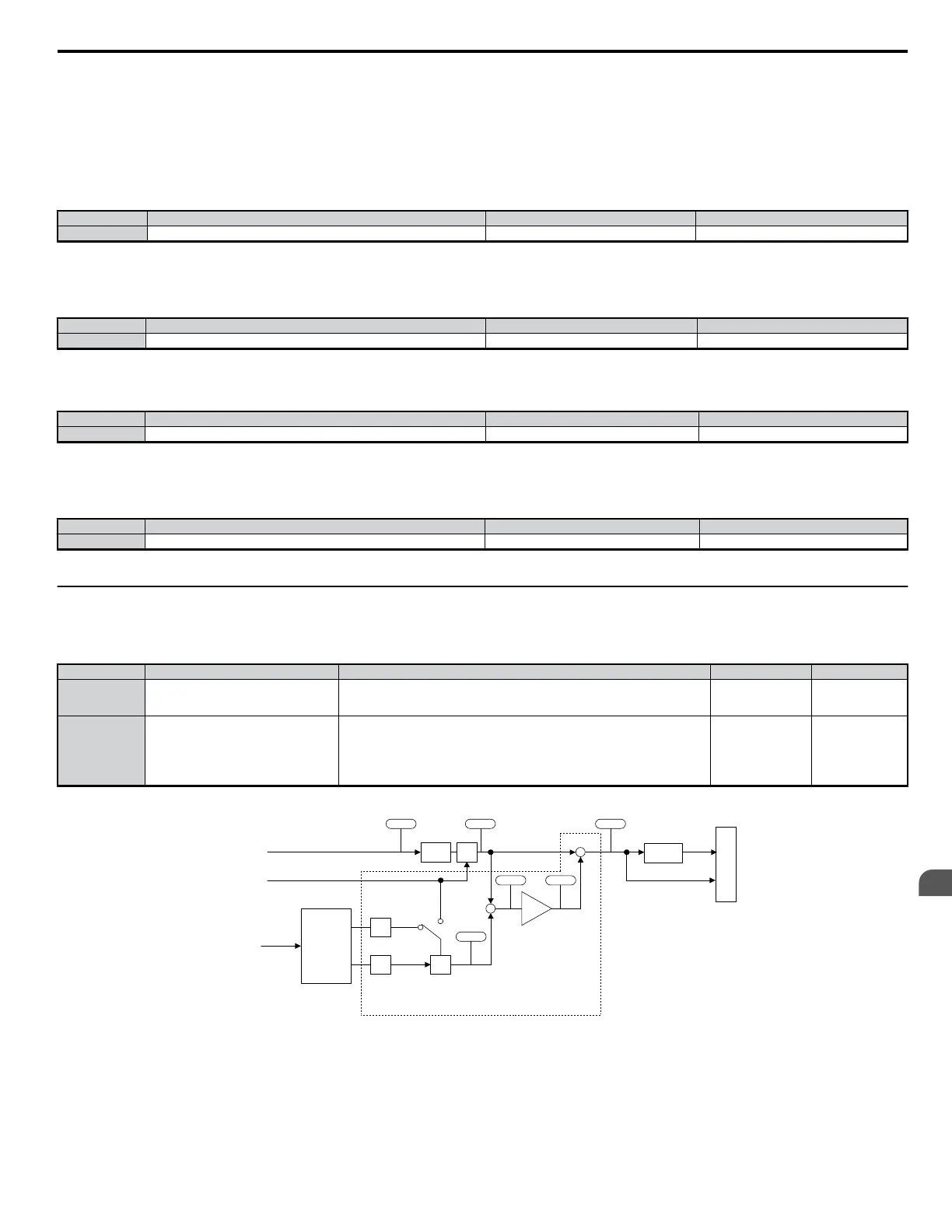
The figure below illustrates how speed control works when using Simple PG in V/f.
Soft
starter
V/f
Conversion
Voltage
Reference
Frequency
Reference
PWM
×
PG/ Pulse
Converter
PI
DI
Frequency
Instruction
Rotation
Direction
Detection
Frequency
Detection
Frequency Detection with sign
ASR
Frequency
Correction
PG Pulse
A/B Signal
U1-01 U1-16
U6-04U6-03
U1-05
C5-01
C5-02
C5-03
C5-04
C5-05
U1-02
×
Positive/
Inverse-instruction
DI Off
DI On
+
_
+
+
Figure 5.26 Speed Control Using Simple V/f with PG
n
C5-01/C5-03: ASR Proportional Gain 1/2 (Simple PG in V/f)
n
C5-02/C5-04:ASR Integral Time 1/2 (Simple PG in V/f)
C5-01 adjusts the speed in response to speed deviation, and softens the effect of changes in load. Speed response increases as the proportional gain is
increased. However, the load may become unstable if the ASR proportional gain is set too high. ASR Proportional Gain 2 is an additional proportional
gain adjustment that can be enabled by either a multi-function contact input (H1-oo = 77) or the ASR switching frequency (C5-07).
5.3 C: Tuning
YASKAWA ELECTRIC SIEP C710606 18A YASKAWA AC Drive – V1000 Technical Manual (Preliminary)
135
5
Parameter Details

 Loading...


