n
Three-phase AC200 V CIMR-V
o2A0030F ~ 0069F
Three-phase AC400 V CIMR-Vo4A00018F ~ 0038F
C
B
A
D
E
F
G
L
H
J
K
I
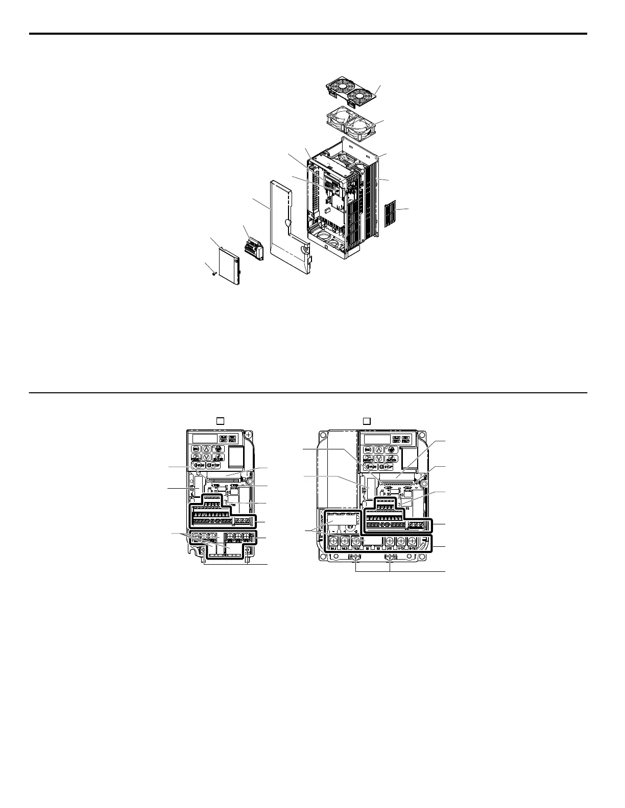
A – Fan cover
B – Cooling fan
Refer to Drive Cooling
Fans on page 261
C – Mounting Hole
D – Heatsink
E – Cable cover
F – Front cover screws
G – Front cover
H – Terminal board Refer to Control
Circuit Terminal Block Functions on
page 44
I – Terminal cover
J – Comm port
K – LED operator Refer to Using the
Digital LED Operator on page 58
L – Case
Figure 1.6 Exploded view of IP20/NEMA Type 1 Components
Three-phase AC400 V CIMR-Vo4A0018F
u
Front Views
I
H
F
A
B
C
D
E
G
I
A
B
C
D
E
F
G
H
CIMR-V 2A0006B CIMR-V 2A0012B
A – Terminal board connector
B – DIP switch S1 Refer to Terminal A2
Switch on page 50
C – DIP switch S3 Refer to Sinking/
Sourcing Mode Switch on page 48
D – Control circuit terminal Refer to
Control Circuit Wiring on page 44
E – Main circuit terminal Refer to Wiring
the Main Circuit Terminal on page
43
F – Ground terminal
G – Terminal cover
H – Option card connector Refer to
Connecting the Option Card on page
279
I – DIP switch S2 Refer to MEMOBUS/
Modbus Termination on page 51
Figure 1.7 Front Views of Drives
1.4 Component Names
22
YASKAWA ELECTRIC SIEP C710606 18A YASKAWA AC Drive – V1000 Technical Manual (Preliminary)

 Loading...


