Model
CIMR-Vo2A
Terminal Screw Size
Tightening
Torque
N•m (lb.in.)
Applicable
Gauge
mm
2
(AWG)
Recommended
Gauge
mm
2
(AWG)
Line Type
0030
R/L1, S/L2, T/L3, U/T1, V/T2, W/T3, -, +1, +2 M4
1.2 to 1.5
(10.6 to 13.3)
5.5 to 14
(10 to 6)
8
(8)
Note 1 on page
41
B1, B2 M4
1.2 to 1.5
(10.6 to 13.3)
2.0 to 5.5
(14 to 10)
5.5
(10)
Note 1 on page
41
M5
2 to 2.5
(17.7 to 22.1)
5.5 to 14
(10 to 6)
8
(8)
Note 1 on page
41
0040
R/L1, S/L2, T/L3, U/T1, V/T2, W/T3, -, +1, +2 M4
1.2 to 1.5
(10.6 to 13.3)
5.5 to 14
(10 to 6)
14
(6)
Note 1 on page
41
B1, B2 M4
1.2 to 1.5
(10.6 to 13.3)
2.0 to 5.5
(14 to 10)
5.5
(10)
Note 1 on page
41
M5
2 to 2.5
(17.7 to 22.1)
5.5 to 14
(10 to 6)
8
(8)
Note 1 on page
41
0056
R/L1, S/L2, T/L3, U/T1, V/T2, W/T3, -, +1, +2 M6
4 to 6
(35.4 to 53.1)
14 to 22
(6 to 4)
22
(4)
Note 1 on page
41
B1, B2 M5
2 to 2.5
(17.7 to 22.1)
5.5 to 8
(10 to 8)
8
(8)
Note 1 on page
41
M6
4 to 6
(35.4 to 53.1)
14 to 22
(6 to 4)
22
(4)
Note 1 on page
41
0069
R/L1, S/L2, T/L3, U/T1, V/T2, W/T3, -, +1, +2 M8
9 to 11
(79.7 to 11.0)
8 to 38
(8 to 2)
38
(2)
Note 1 on page
41
B1, B2 M5
2 to 2.5
(17.7 to 22.1)
8 to 14
(8 to 6)
14
(6)
Note 1 on page
41
M6
4 to 6
(35.4 to 53.1)
8 to 22
(8 to 4)
22
(4)
Note 1 on page
41
n
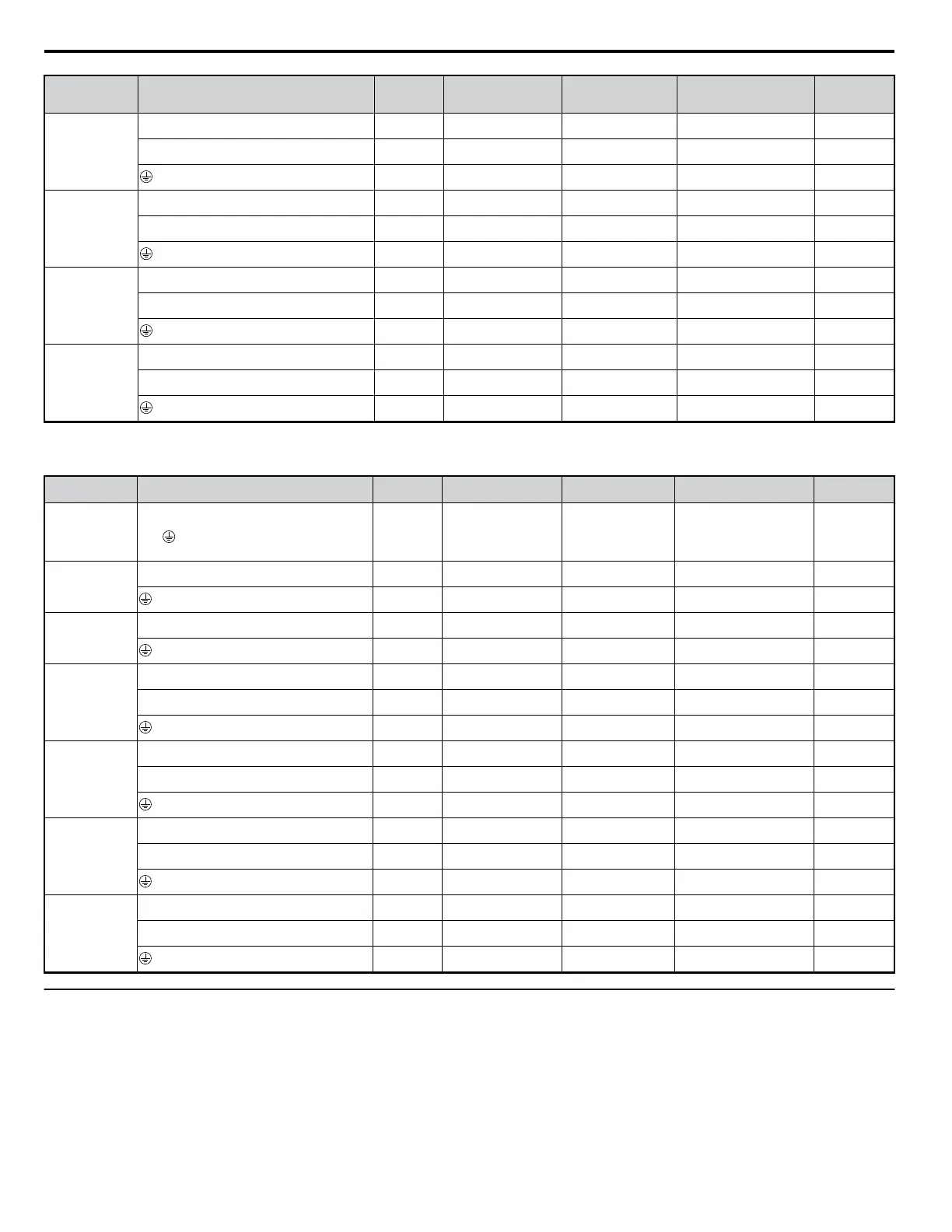
Three-Phase 400 V Class
Table 3.4 Wire Gauge and Torque Specifications
Model
CIMR-Vo4A
Terminal Screw Size
Tightening Torque
N•m (lb.in.)
Applicable Gauge
mm
2
(AWG)
Recommended Gauge
mm
2
(AWG)
Line Type
0001
0002
0004
0005
0007
R/L1, S/L2, T/L3, U/T1, V/T2, W/T3, –, +1, +2, B1,
B2,
M4
1.2 to 1.5
(10.6 to 13.3)
2.0 to 5.5
(14 to 10)
2
(14)
Note 1 on page
41
0009
R/L1, S/L2, T/L3, U/T1, V/T2, W/T3, –, +1, +2, B1,
B2
M4
1.2 to 1.5
(10.6 to 13.3)
2.0 to 5.5
(14 to 10)
2
(14)
Note 1 on page
41
M4
1.2 to 1.5
(10.6 to 13.3)
2.0 to 5.5
(14 to 10)
3.5
(12)
Note 1 on page
41
0011
R/L1, S/L2, T/L3, U/T1, V/T2, W/T3, –, +1, +2, B1,
B2
M4
1.2 to 1.5
(10.6 to 13.3)
2.0 to 5.5
(14 to 10)
2
(14)
Note 1 on page
41
M4
1.2 to 1.5
(10.6 to 13.3)
2.0 to 5.5
(14 to 10)
3.5
(12)
Note 1 on page
41
0018
R/L1, S/L2, T/L3, U/T1, V/T2, W/T3, -, +1, +2 M4
1.2 to 1.5
(10.6 to 13.3)
2.0 to 5.5
(14 to 10)
5.5
(10)
Note 1 on page
41
B1, B2 M4
1.2 to 1.5
(10.6 to 13.3)
2.0 to 5.5
(14 to 10)
5.5
(10)
Note 1 on page
41
M5
2 to 2.5
(17.7 to 22.1)
5.5 to 14
(10 to 6)
5.5
(10)
Note 1 on page
41
0023
R/L1, S/L2, T/L3, U/T1, V/T2, W/T3, -, +1, +2 M4
1.2 to 1.5
(10.6 to 13.3)
5.5 to 14
(10 to 6)
8
(8)
Note 1 on page
41
B1, B2 M4
1.2 to 1.5
(10.6 to 13.3)
2.0 to 5.5
(14 to 10)
5.5
(10)
Note 1 on page
41
M5
2 to 2.5
(17.7 to 22.1)
5.5 to 14
(10 to 6)
5.5
(10)
Note 1 on page
41
0031
R/L1, S/L2, T/L3, U/T1, V/T2, W/T3, -, +1, +2 M5
2 to 2.5
(17.7 to 22.1)
5.5 to 14
(10 to 6)
8
(8)
Note 1 on page
41
B1, B2 M5
2 to 2.5
(17.7 to 22.1)
5.5 to 8
(10 to 8)
8
(8)
Note 1 on page
41
M6
4 to 6
(35.4 to 53.1)
5.5 to 14
(10 to 6)
8
(8)
Note 1 on page
41
0038
R/L1, S/L2, T/L3, U/T1, V/T2, W/T3, -, +1, +2 M5
2 to 2.5
(17.7 to 22.1)
5.5 to 14
(10 to 6)
14
(6)
Note 1 on page
41
B1, B2 M5
2 to 2.5
(17.7 to 22.1)
5.5 to 8
(10 to 8)
8
(8)
Note 1 on page
41
M6
4 to 6
(35.4 to 53.1)
5.5 to 14
(10 to 6)
8
(8)
Note 1 on page
41
u
Main Circuit Terminal Power Supply and Motor Wiring
This section outlines the various steps, precautions, and checkpoints for wiring the main circuit terminals and motor terminals.
NOTICE: When connecting the motor to the drive output terminals U/T1, V/T2, and W/T3, the phase order for the drive and motor should match. Failure to comply with proper
wiring practices may cause the motor to run in reverse if the phase order is backward.
NOTICE: Do not connect phase-advancing capacitors or LC/RC noise filters to the output circuits. Improper application of noise filters could result in damage to the drive.
NOTICE: Do not connect the AC power line to the output motor terminals of the drive. Failure to comply could result in death or serious injury by fire as a result of drive damage
from line voltage application to output terminals.
3.6 Main Circuit Wiring
42
YASKAWA ELECTRIC SIEP C710606 18A YASKAWA AC Drive – V1000 Technical Manual (Preliminary)

 Loading...


