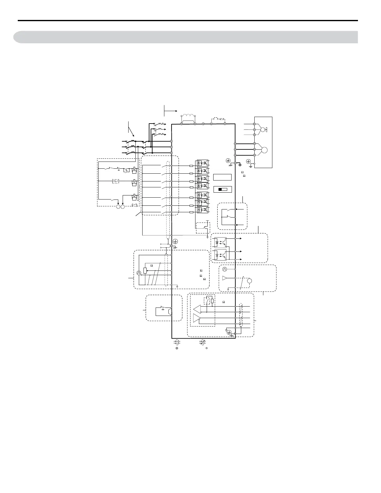
3.2 Standard Connection Diagram
Connect the drive and peripheral devices as shown in
Figure 3.1 . It is possible to run the drive via the digital operator without connecting digital I/O
wiring. This section does not discuss drive operation; Refer to Start-Up Programming & Operation on page 55 for instructions on operating the drive.
NOTICE: Inadequate branch short circuit protection could result in damage to the drive. Install adequate branch circuit short circuit protection per applicable codes. The drive is
suitable for circuits capable of delivering not more than 30,000 RMS symmetrical amperes, 240 Vac maximum (200 V Class) and 480 Vac maximum (400 V Class).
NOTICE: When the input voltage is 480 V or higher or the wiring distance is greater than 100 meters, pay special attention to the motor insulation voltage or use an inverter duty
motor. Failure to comply could lead to motor insulation breakdown.
NOTICE: Do not connect the AC control circuit ground to the drive enclosure. Improper drive grounding can cause the control circuit to malfunction.
NOTICE: The minimum load for the multi-function relay output MA-MB-MC is 10 mA. If a circuit requires less than 10 mA (reference value), connect it to a photocoupler output (P1,
P2, PC). Improper application of peripheral devices could result in damage to the photocoupler output of the drive.
SA
Motor
Cooling fan
Forward run/stop
Reverse run/stop
External fault
Fault reset
Multi-step
speed 2
Jog reference
0 to +10 Vdc
(2 mA)
DIP
switch S3
DC reactor
(option)
Digital inputs
(default setting)
Comm.
connector
Safe Disable
Input
Safety switch
Fault
V1000
Shield ground
terminal
Thermal relay
(option)
Braking resistor
(option)
Main circuit
Control circuit
Thermal relay for
motor cooling fan
Fault relay
1 MCCB
MC
2 MCCB
r1
s1
t1
R/L1
S/L2
T/L3
S1
S2
S3
S4
S5
S6
S7
*3
*
1
*
2
-
B1+1+2 B2
*
4
R/L1
S/L2
T/L3
MC
THRX
TRX
MC
TRX
MC MA
U/T1
V/T2
W/T3
24 V
0 V
MA
P1
MB
MC
V I
+
24 V 8 mA
*
5
M
M
r1
s1
t1
FU
FV
FW
U
V
W
SC
P2
MP
AM
AC
PC
IG
R
+
R
-
S
+
S
-
+
-
AM
HC
H1
RP
+V
A1
A2
AC
*
7
*
6
Pulse train input
(max. 32 kHz)
Ground
10 or less (400 V class)
100 or less (200 V class)
0 to +10 V (20 k )
Setting power supply
+10.5 max. 20 mA
0 to +10 V (20 k )
(0)4 to 20 mA (250 )
For single phase 200 V
power supply, use
R/L1 and S/L2.
During Run
(photocoupler 1)
Frequency agree
(photocoupler 2)
Photocoupler
output common
Digital output
5 ~ 48 Vdc
2 to 50 mA
(default setting)
Pulse train output
0 to 32 kHz
Analog monitor
output
Digital output
250 Vac, 10 mA to 1 A
30 Vdc, 10 mA to 1 A
(default setting)
MEMOBUS/
Modbus comm.
RS-485/422
Main speed
frequency
reference.
Multi-function
programmable
Multi-step
speed 1
main/aux switch
2 MCCB
THRX
OFF
ON
MC
SA
SA
Three phase
power supply
200 to 240 V
Jumper
DIP switch S1
Sink
Source
Termination
resistor
120 , 1/2 W
Terminals +1, +2, , B1, and B2
are for connecting options.
Never connect power supply
lines to these terminals.
_
Monitor
output
*
8
Jumper
Option card
connector
DIP
switch
S2
main circuit terminal
shielded line
twisted-pair shielded line
control terminal
Cable shield ground
2 k
Figure 3.1 Drive Standard Connection Diagram
*1. Remove the jumper when installing an optional DC reactor.
*2. The MC on the input side of the main circuit should open when the thermal relay is triggered.
*3. Self-cooled motors do not require separate cooling fan motor wiring.
*4. Connected using sequence input signal (S1 to S7) from NPN transistor; Default: sink mode (0 V com)
*5. Use only a +24 V internal power supply in sinking mode; the source mode requires an external power supply.
Refer to I/O Connections on page 48.
*6. Minimum load: 5 Vdc, 10mA (reference value)
*7. Monitor outputs work with devices such as analog frequency meters, ammeters, voltmeters and wattmeters; they are intended for use as a feedback-type of signal.
*8. Disconnect the wire jumper between HC and H1 when utilizing the safety input.
WARNING! Sudden Movement Hazard. Do not close the wiring for the control circuit unless the multifunction input terminal parameter is properly set (S5 for 3-wire; H1-05 = “0”).
Improper sequencing of run/stop circuitry could result in death or serious injury from moving equipment.
WARNING! Sudden Movement Hazard. Ensure start/stop and safety circuits are wired properly and in the correct state before energizing the drive. Failure to comply could result
in death or serious injury from moving equipment. When programmed for 3-wire control, a momentary closure on terminal S1 may cause the drive to start.
WARNING! When 3-Wire sequence is used, set the drive to 3-Wire sequence before wiring the control terminals and ensure parameter b1-17 is set to 0 (drive does not accept a
run command at power up (default)). If the drive is wired for 3-Wire sequence but set up for 2-Wire sequence (default) and if parameter b1-17 is set to 1 (drive accepts a Run
command at power up), the motor will rotate in reverse direction at power up of the drive and may cause injury.
3.2 Standard Connection Diagram
34
YASKAWA ELECTRIC SIEP C710606 18A YASKAWA AC Drive – V1000 Technical Manual (Preliminary)

 Loading...


