3.4 Terminal Block Configuration
The figures in this section provide quick reference and detailed illustrations of the main and control circuit terminal block configurations.
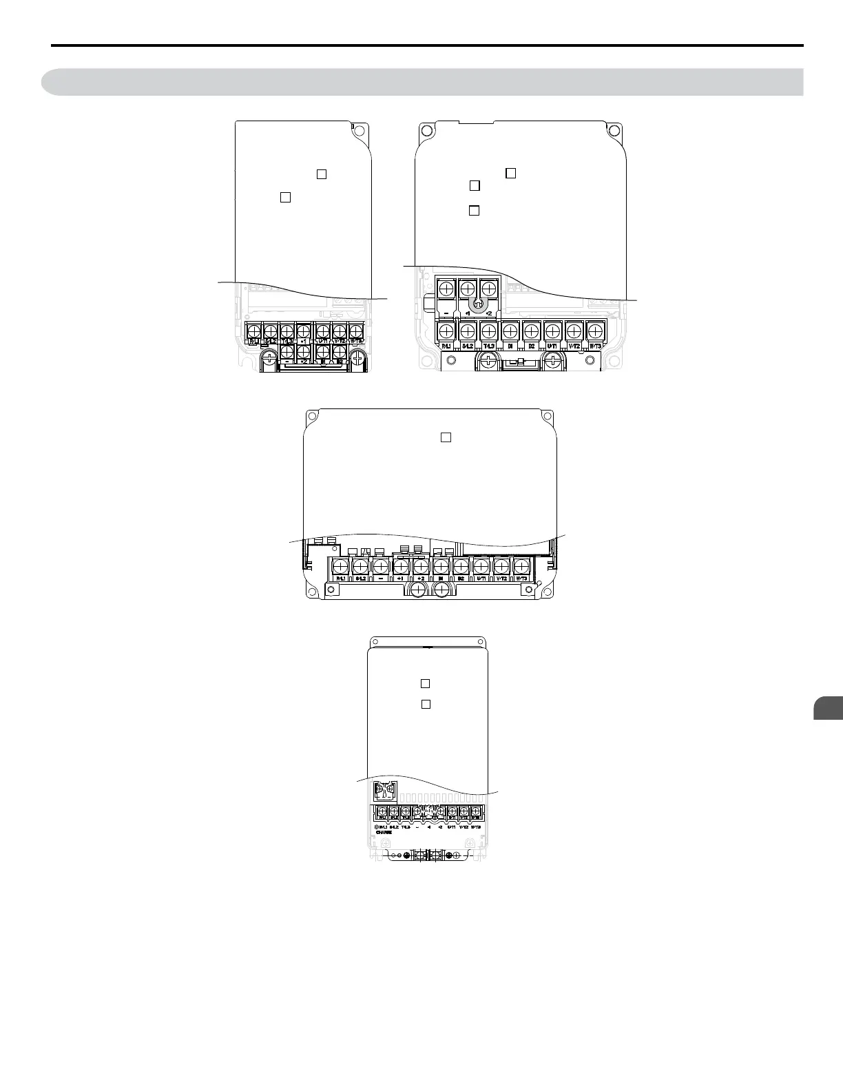
Models CIMR-V BA0001,
CIMR-V 2A0001, 0002,
0004, 0006
0002, 0003
Models CIMR-V BA0006, 0010, 0012
CIMR-V 2A0010, 0012, 0020, 0040,
0056, 0069
CIMR-V 4A0001, 0002, 0004, 0005,
0007, 0009, 0011, 0023, 0031, 0038
Figure 3.5 Main Circuit Terminal Block Configurations
Models CIMR-V BA0018
Figure 3.6 Main Circuit Terminal Block Configurations
Models
CIMR-V 2A0030,
CIMR-V 4A0018,
0023
0040
Figure 3.7 Main Circuit Terminal Block Configurations
3.4 Terminal Block Configuration
YASKAWA ELECTRIC SIEP C710606 18A YASKAWA AC Drive – V1000 Technical Manual (Preliminary)
37
3
Electrical Installation

 Loading...


