No. Parameter Name Setting Range Default
b1-15
Frequency Reference
2
Selects the frequency reference input source.
0: Operator - Digital preset speed U1-01 or d1-01 to d1-17.
1: Terminals - Analog input terminal A1 (or terminal A2 based on parameter H3-09).
2: Serial Com - Modbus RS-422/485 terminals R+, R-, S+ and S-.
3: Option PCB4: Pulse Input (Terminal RP)
0
n
b1-16: Run Command Source 2
Refer to the detailed description for parameter b1-02.
No. Parameter Name Setting Range Default
b1-16 Run Command Source 2
Selects the run command input source.
0: Operator - RUN and STOP keys on the digital operator.
1: Terminals - Contact closure on terminals S1 or S2.
2: Serial Com - Modbus RS-422/485 terminals R+, R-, S+ and S-.
3: Option PCB
0
n
b1-17: Run Command at Power Up
Determines whether a run command is given as soon as the power to the drive is switched on.
No. Parameter Name Setting Range Default
b1-17 Run Command at Power Up
0: No run command issued at power up
1: Run command given when power is switched on
0
CAUTION! The motor will begin rotating immediately after the power is switched on. Take proper precautions to ensure the area around the motor is safe prior to powering up the
drive. Failure to comply may cause injury.
Note: The drive is initially set up not to accept a run command at power up (b1-17 = 0). If a run command is issued at power up, the RUN indicator LED will flash quickly. For the
drive to issue the run command, change b1-17 = “1”.
u
b2: DC Injection Braking
These parameters determine how the DC Injection Braking feature operates. Parameters involving the starting frequency, current level, braking time, and
motor pre-heat current level are located here.
n
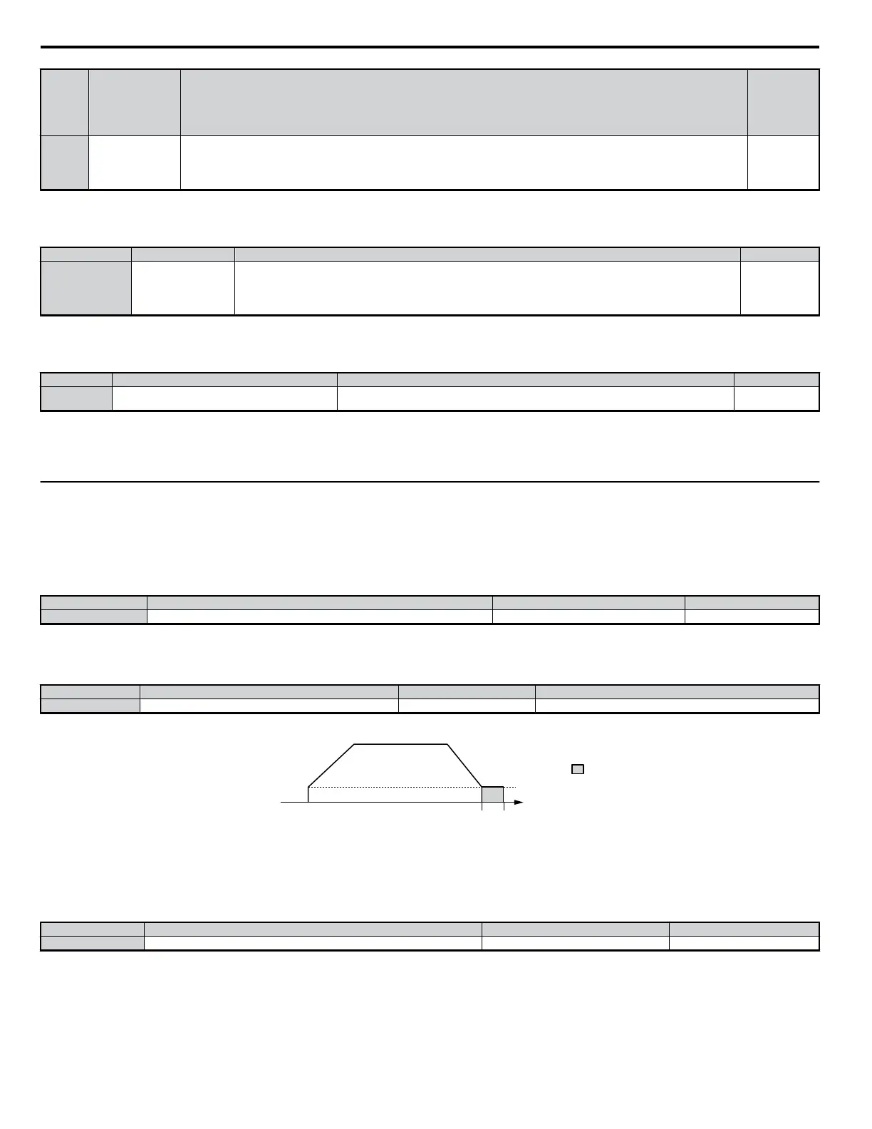
b2-01: DC Injection Braking Start Frequency
Sets the frequency at which DC Injection Braking starts when “Ramp to Stop” is selected as the stopping method (b1-03 = 0). Set in Hz.
No. Name Setting Range Default
b2-01 DC Injection Braking Start Frequency 0.0 to 10.0 0.5
Detailed Description
Parameter b2-01 sets the output frequency at which the drive begins DC Injection during ramp to stop in order to lock the rotor of the motor and established
the end point of the ramp. If b2-01 < E1-09 (Minimum Frequency), then DC Injection begins at at the frequency set to E1-09.
No. Name Setting Range Default
E1-09 Minimum Output Frequency (FMIN) 0.0 to 400.0* Determined by A1-02 and C1-03. OLV for PM relies on E5-01.
*The upper limit for the setting range is determined by E1-04. E5-01 determines the default value when using PM Open Loop Vector.
b2-04
b2-01
DC Injection Braking
start frequency
output
frequency
braking time
Figure 5.8 DC Injection Braking during Deceleration
n
b2-02: DC Injection Braking Current
Sets the DC Injection Braking current as a percentage of the drive rated current. If set to larger than 50%, the carrier frequency is automatically reduced
to 1 kHz.
No. Parameter Name Setting Range Default
b2-02 DC Injection Braking Current 0 to 75 50
Detailed Description
The level of DC Injection Braking current affects the strength of the magnetic field attempting to lock the motor shaft. Increasing the level of current will
increase the amount of heat generated by the motor windings, and should only be increased to the level necessary to hold the motor shaft. DC Injection
current is set as a percentage of drive rated output current. Find the drive rated output current by looking at the information listed on the drive nameplate.
n
b2-03: DC Injection Braking Time at Start
Sets the time of DC Injection Braking at start in units of 0.01 s, and is used to stop a coasting motor. Disabled when set to 0.00 s.
5.2 b: Setup
116
YASKAWA ELECTRIC SIEP C710606 18A YASKAWA AC Drive – V1000 Technical Manual (Preliminary)

 Loading...


