Setting 90 to 92: DriveWorksEZ Digital Output 1 to 3
For use with DriveWorksEZ.
Setting 100 to 192: Reverse Switching for Functions 0 to 92
Reverses the switching status of the specified terminal and function. Set as 1oo, where the last two digits specify the setting number of the function to
be reversed.
Example: To reverse the output for “8: During Baseblock”, set “108”. To reverse the output for “14A: During KEB,” set 14A.
n
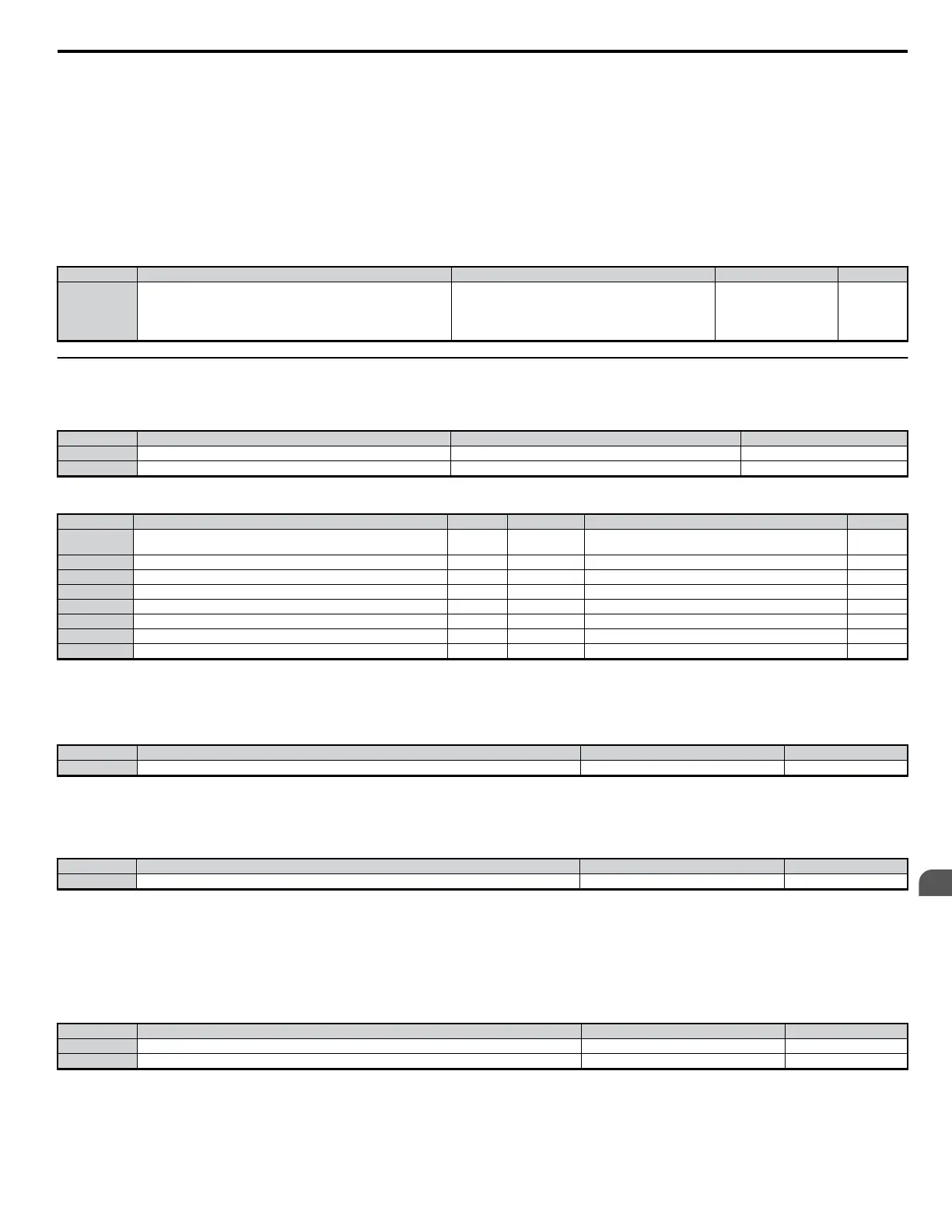
H2-06: Watt Hour Output Unit Selection
When one of the multi-function terminals is set output the number of watt hours (H2-01 to H2-03 = 39), parameter H2-06 determines the units for the
output signal. Outputs a signal every 200 ms.
No. Parameter Name Setting Range Default Page
H2-06 Watt Hour Output Unit Selection
0: 0.1 kWH units
1: 1 kWH units
2: 10 kWH units
3: 100 kWH units
4: 1000 kWH units
0 −
u
H3: Multi-Function Analog Input Terminals
The drive is equipped with 2 multi-function analog input terminals, A1 and A2. The user can assign functions to these terminals by setting parameters
H3-02 and H3-10 between 0 and 31.
No. Parameter Name Setting Range Default
H3-02 Terminal A1 Function Selection 0 to 31 0
H3-10 Terminal A2 Function Selection 0 to 31 0
n
Multi-Function Analog Input Terminal Settings
Setting Function Page Setting Function Page
0 Frequency Bias (A1) − F
Not used (use this setting if the terminal is not used or is used
as a pass-through terminal)
−
1 Frequency Gain − 10 FWD Torque Limit −
2 Auxiliary Frequency Reference (used as a second frequency reference) − 11 REV Torque Limit −
4 Output Voltage Bias − 12 Regenerative Torque Limit −
7 Overtorque/Undertorque Detection Level − 15 FWD/REV Torque Limit −
B PID Feedback − 16 Differential PID Feedback −
C PID Set Point − 30 DriveWorksEZ Analog Input 1 −
E Motor Temperature (PTC input) − 31 DriveWorksEZ Analog Input 2 −
Analog input levels are set using the H3 parameters described below.
n
H3-01: Terminal A1 Signal Level Selection
The A1 analog input can accept either a 0 to 10 Vdc or -10 to +10 Vdc signal as a reference.
No. Parameter Name Setting Range Default
H3-01 Terminal A1 Signal Level Selection 0 to 1 0
Note: When set to “1”, the user can have an input of less than 5 V can be treated as a negative value by tuning the gain and bias levels.
n
H3-02: Terminal A1 Function Selection
Determines the function assigned to analog output terminal A1.
No. Parameter Name Setting Range Default
H3-02 Terminal A1 Function Selection 0 to 31 0
Note: If not using an input terminal or if using it in the through-mode, be sure to set that terminal to “F”.
n
H3-03: Terminal A1 Gain Setting
n
H3-04: Terminal A1 Bias Setting
In order to have the drive properly interpret an analog input, it may be necessary to apply a gain and/or a bias to the signal. The analog inputs have a
resolution of 10 bits (1024 steps).
No. Parameter Name Setting Range Default
H3-03 Terminal A1 Gain Setting -999.9 to 999.9 100.0%
H3-04 Terminal A1 Bias Setting -999.9 to 999.9 0.0%
Detailed Description
Using the factory default settings for the analog input’s gain and bias, the 0 to 10 Vdc or the -10 to +10 Vdc signal at the analog input will yield a 0 to
100% frequency reference span.
5.7 H: Terminal Functions
YASKAWA ELECTRIC SIEP C710606 18A YASKAWA AC Drive – V1000 Technical Manual (Preliminary)
179
5
Parameter Details

 Loading...


