4.7 Test Run
u
Powering Up the Drive and Operation Status Display
n
Powering Up the Drive
Review the following checklist before turning the power on.
Item to Check Description
Power supply voltage
Ensure the power supply voltage is correct:
200 V class: single-phase 200 to 240 Vac 50/60 Hz
200 V class: 3-phase 200 to 240 Vac 50/60 Hz
400 V class: 3-phase 380 to 480 Vac 50/60 Hz
Properly wire the power supply input terminals (R/L1, S/L2, T/L3).
(for single-phase 200 V class models, wire only R/L1 and S/L2)
Check for proper grounding of drive and motor.
Drive output terminals and motor
terminals
Properly wire drive output terminals U/T1, V/T2, and W/T3 with motor terminals U, V, and W.
Control circuit terminals Check control circuit terminal connections.
Drive control terminal status Open all control circuit terminals (off).
Status of the load and connected
machinery
Uncouple the motor from the load.
n
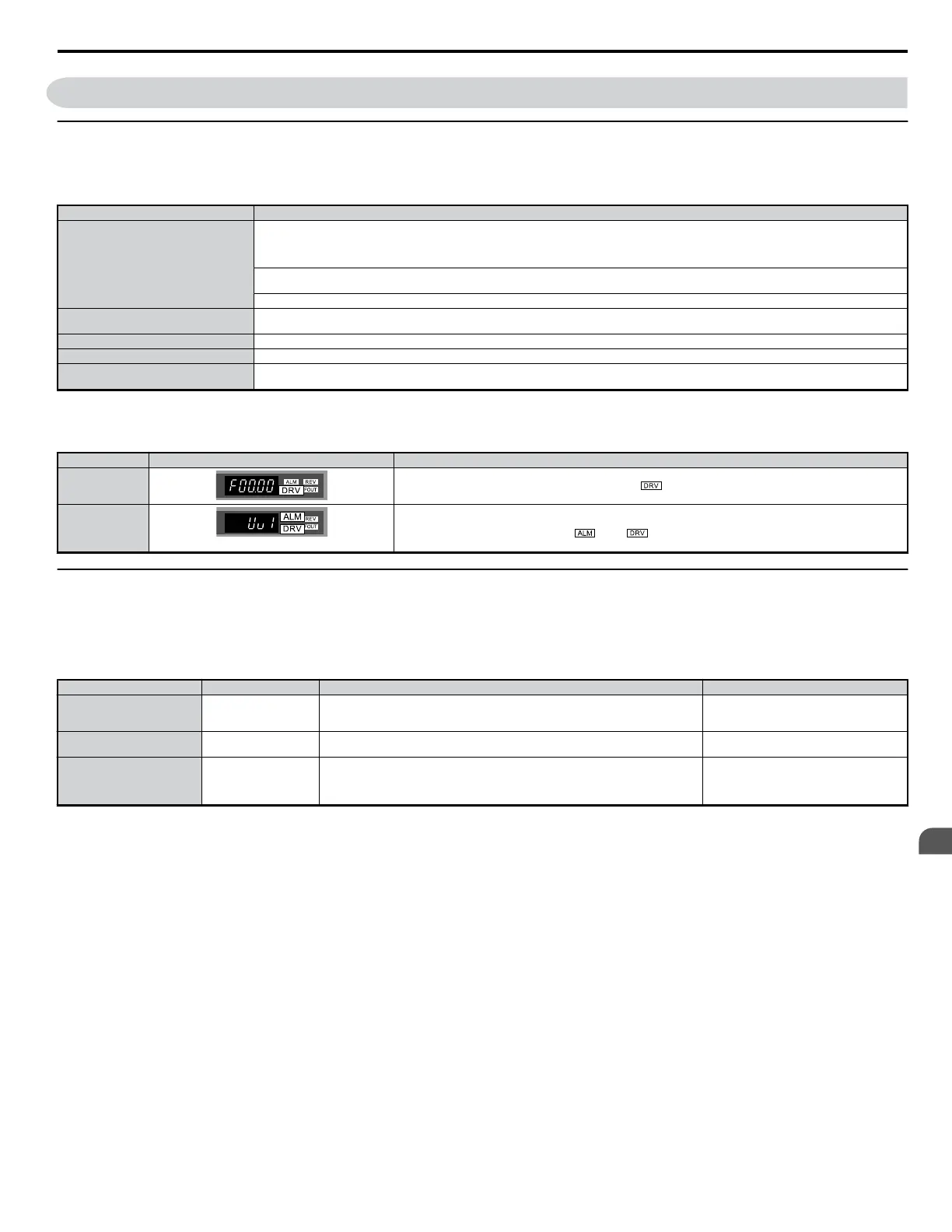
Status Display
When the power supply to the drive is turned on, the LED operator lights will appear as follows:
No. Name Description
Normal Operation
The data display area displays the frequency reference. flashes.
Fault
Main circuit low voltage (ex)
Data displayed varies by the type of fault. Refer to Fault Displays, Causes, and Possible Solutions on page 229 for
more information and corrective action. and are lit.
u
Auto-Tuning
Auto-Tuning automatically sets and tunes parameters required for motor operation.
n
Types of Auto-Tuning
There are three types of Auto-Tuning.
Refer to Auto-Tuning Selection on page 92 to select the best type of Auto-Tuning for the application.
Type Setting Application Conditions and Benefits Control Mode
Rotational Auto-Tuning for V/
f Control
T1-01 = 3
Assumes the motor can rotate during the Auto-Tuning process
Improves torque compensation, slip compensation, energy savings, and speed search
performance
V/f Control
Rotational
Auto-Tuning for OLV Control
T1-01 = 0
Assumes the motor can rotate during the Auto-Tuning process
Achieves high-performance motor control
Open Loop Vector Control
Stationary Auto-Tuning for V/
f and OLV Control Line-to-
Line Resistance Only
T1-01 = 2
For use when the motor cable exceeds 50 m
The motor cable length has been modified after Auto-Tuning has been previously
performed
When motor capacity and drive capacity differ
V/f Control, Open Loop Vector Control
Note: Auto-Tuning cannot be performed on permanent magnet motors (IPM, SPM, etc.).
4.7 Test Run
YASKAWA ELECTRIC SIEP C710606 18A YASKAWA AC Drive – V1000 Technical Manual (Preliminary)
91
4
Start-Up Programming
& Operation

 Loading...


