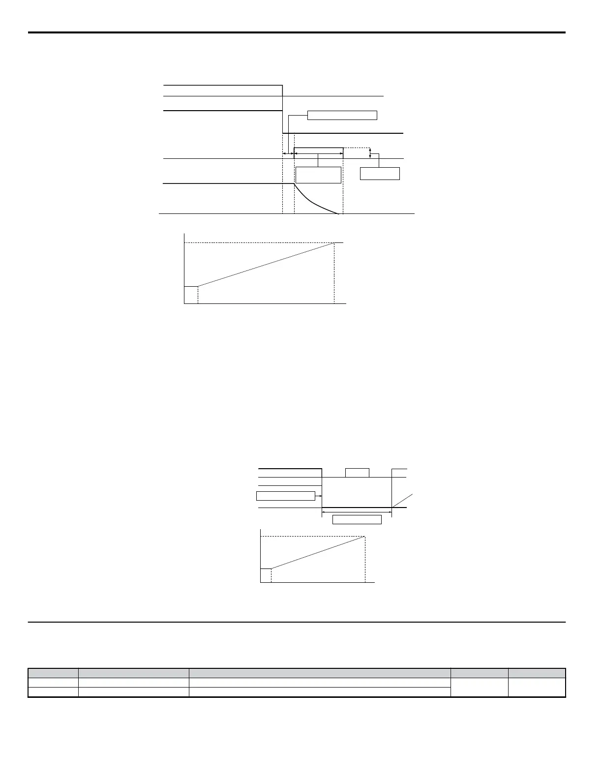
Run Command
Output Frequency
ON OFF
DC Injection Braking
Time at Stop
(b2-04)*
Minimum Baseblock Time (
L2-03)
DC Braking
Current (b2-02)
DC Injection Braking
Motor Speed
Output frequency when
stop command was entered
100%
(Max Output Frequency)
10%
DC Injection Braking Time
b2-04 x 10
b2-04
Figure 4.19 DC Injection Braking Stop
*See
Figure 4.18
Note: Extend baseblock time (L2-03) if overcurrent (OC) occurs on stop command input.
n
Coast to Stop with Timer: Ignoring a Run Command Input within the Deceleration Time: b1-03 = 3
When b1-03 = 3, a stop command interrupts drive output and the motor coasts to stop. The drive will not accept the next run command until time “t” has
passed. Time “t” is determined by the output frequency at the moment the stop command was entered and the deceleration time set to the drive according
to
Figure 4.20 .
Drive output voltage interrupted
Operation Wait Time t
Run Command
Output Frequency
ON ON ONOFF OFF
Minimum Output Frequency
100%
(Max Output Frequency)
Output frequency when
stop command was entered
Operation wait time t
Deceleration time
(C1-02, etc.)
Minimum
Baseblock Time
(L2-03)
Figure 4.20 Coast to Stop with Timer
u
Acceleration/Deceleration: C1-01 to C1-11
C1-01 (Acceleration Time 1) sets the time to accelerate from 0 to the maximum output frequency (E1-04). C1-02 (Deceleration Time 1) sets the time to
decelerate from maximum output frequency to 0.
No. Parameter Name Description Setting Range Default
C1-01 <1> Acceleration Time 1 Sets the time to accelerate from 0 to 100% (maximum output frequency).
0.0 to 6000.0 <2> 10.0 s
C1-02 <1> Deceleration Time 1 Sets the time to decelerate from 100% (maximum output frequency) to 0%.
4.6 Basic Drive Setup Adjustments
80
YASKAWA ELECTRIC SIEP C710606 18A YASKAWA AC Drive – V1000 Technical Manual (Preliminary)

 Loading...


