C6-03
C6-04
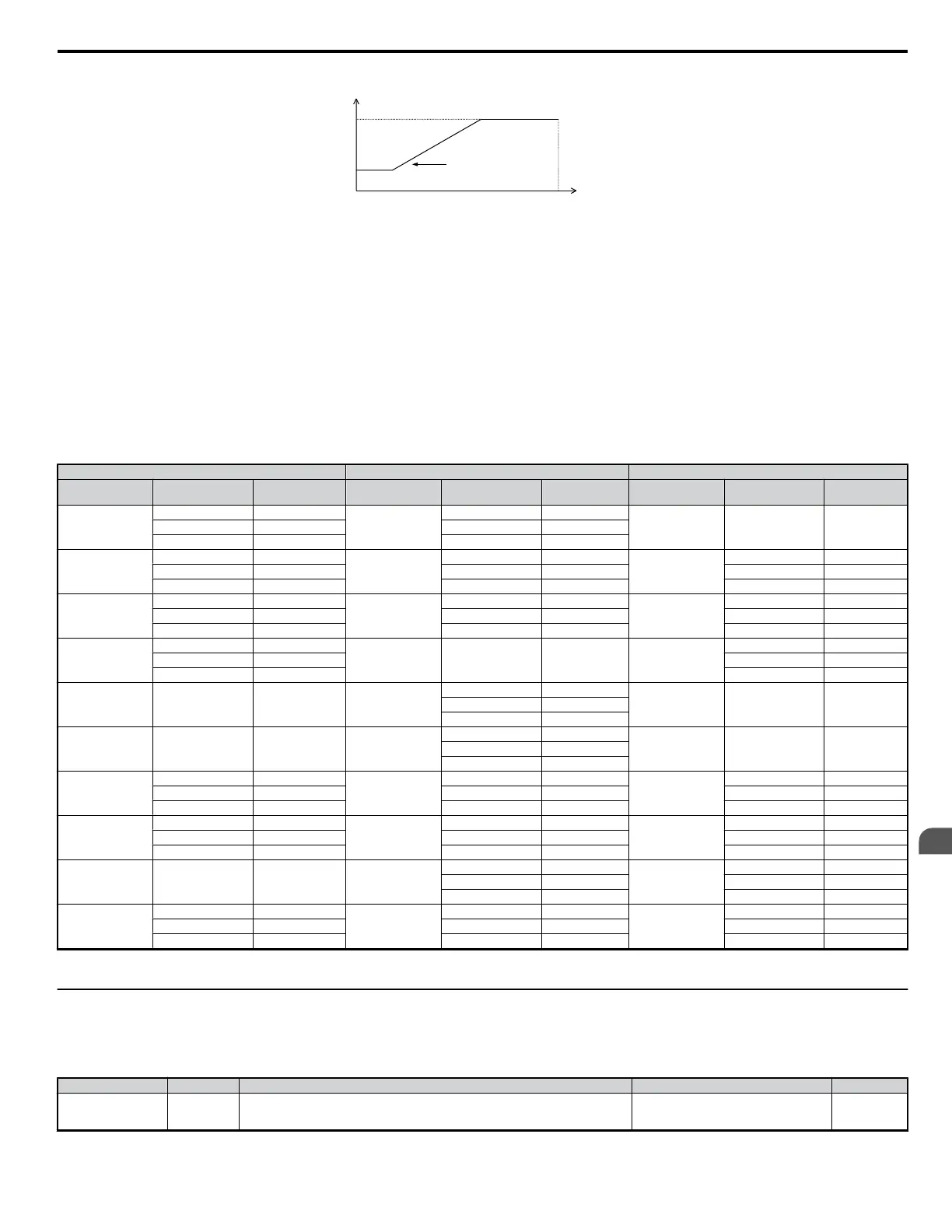
Output Frequency
E1-04
Maximum Output Frequency
* The value of coefficient K is determined by the value of C6-03.
C6-03 ≥ 10.0 kHz : K=3
Carrier Frequency
Output Frequency
x (C6-05) x K
10.0 kHz > C6-03 ≥ 5.0 kHz : K=2
5.0 kHz > C6-03 : K=1
Figure 4.23 Carrier Frequency Changes Relative to Output Frequency
Note: For Open Loop Vector Mode, A1-02 = 2 and OLV for PM the carrier frequency is fixed to a value set by C6-02 or C6-03 if C6-02 is set to F (programmable).
Carrier Frequency Setting Error (oPE11)
A carrier frequency setup error (oPE11) will occur when carrier frequency gain (C6-05) is greater than 6 and C6-03 < C6-04.
Note:
Refer to Troubleshooting Without Fault Display on page 248 for information on operator errors (oPE).
n
Carrier Frequency and Drive Overload Current Level
With C6-01 set to 1, the carrier frequency setting defines drive output current level.
Table 4.19 Current Derating by Carrier Frequency Setting
Single-Phase 200 V Three-Phase 200 V Three-Phase 400 V
Model (Capacity)
Carrier Frequency
(kHz)
Output Current
(A)
Model (Capacity)
Carrier Frequency
(kHz)
Output Current
(A)
Model (Capacity)
Carrier Frequency
(kHz)
Output Current
(A)
Bo0001
0.2 kW/
0.1 kW
2 1.2
2o0001
0.2 kW/
0.1 kW
2 1.2
10 0.8 10 0.8
15 0.6 15 0.6
Bo0002
0.4 kW/
0.2 kW
2 1.9
2o0002
0.4 kW/
0.2 kW
2 1.9
4o0001
0.4 kW/
0.2 kW
2 1.2
10 1.6 10 1.6 8 1.2
15 1.3 15 1.3 15 0.7
Bo0003
0.75 kW/
0.4 kW
2 3.3
2o0004
0.75 kW/
0.4 kW
2 3.3
4o0002
0.75 kW/
0.4 kW
2 2.1
10 3.0 10 3.0 8 1.8
15 2.4 15 2.4 15 1.1
Bo0006
1.1 kW/
0.75 kW
2 6.0
4o0004
1.5 kW/
0.75 kW
2 4.1
10 5.0 8 3.4
15 4.0 15 2.0
2o0006
1.1 kW/
0.75W
2 6.0
10 5.0
15 4.0
2o0008
1.5 kW/
1.1 kW
2 8.0
8 6.9
15 5.5
Bo0010
2.2 kW/
1.5W
2 9.6
2o0010
2.2 kW/
1.5W
2 9.6
4o0005
2.2 kW/
1.5W
2 5.4
8 8.0 8 8.0 8 4.8
15 6.4 15 6.4 15 2.9
Bo0012
3.0 kW/
2.2 kW
2 12.0
2o0012
3.0 kW/
2.2 kW
2 12.0
4o0007
3.0 kW/
2.2 kW
2 6.9
8 11.0 8 11.0 8 5.5
15 8.8 15 8.8 15 3.3
2o0018
3.7 kW/
3.0W
2 17.5
4o0009
3.7 kW/
3.0 kW
2 8.8
8 14.0 8 7.2
15 11.2 15 4.3
BA0018*
—/
3.7 kW
2 17.5
2o0020
5.5 kW/
4.0 kW
2 19.6
4o0011
5.5 kW/
4.0 kW
2 11.1
8 17.5 8 17.5 8 9.2
15 14.0 15 14.0 15 5.5
* CIMR-VoBA0018 is available with a Heavy Duty rating only.
u
Drive Input Voltage Setting: E1-01
Set E1-01 according to the power supply voltage. This setting serves as a base value for certain drive protective functions.
NOTICE: Set drive input voltage (not motor voltage) in parameter E1-01 for proper function of the protective features of the drive. Failure to comply could result in improper drive
operation. Set parameter E1-01 to match the input voltage of the drive.
Parameter Name Description Setting Range Default
E1-01
Input Voltage
Setting
Set to the nominal voltage of the incoming line. Sets the maximum and base voltage used
by preset V/f patterns (E1-03), and adjusts the levels of drive protective features (e.g.,
overvoltage, braking resistor level, stall prevention, etc.).
200 V Class: 155 to 255
400 V Class: 310 to 510
230 V
4.6 Basic Drive Setup Adjustments
YASKAWA ELECTRIC SIEP C710606 18A YASKAWA AC Drive – V1000 Technical Manual (Preliminary)
83
4
Start-Up Programming
& Operation

 Loading...


