Setting A1-07 to “1” allows the drive to connect to the DriveWorksEZ software package. When using DriveWorksEZ, be sure to set one of the multi-
function terminal inputs for DrivesWorksEZ (H1-oo = “9F”). This drive is ready to communicate with the software when the terminal is open. Set A1-07
to “0” when DriveWorksEZ is not used.
If DriveWorksEZ assigned functions to any multi-function output terminals, those functions stay set after disabling or disconnecting DriveWorksEZ.
No. Parameter Name Setting range Default
A1-07 DriveWorksEZ Function Selection
0: Disabled
1: Enabled
2: Terminal input switch (requires that H1-XX = 9F)
0
u
Frequency Reference Source: b1-01
This section explains how to assign the frequency reference. Parameters b1-01 and b1-02 can be used to select the source of the run command and the
frequency reference independently (e.g., set the reference from the operator and set the run command from the terminals).
n
Frequency Reference from the LED Operator: b1-01 = 0
When b1-01 = 0 the frequency reference will be provided by the LED operator.
Refer to The Drive and Programming Modes on page 61 for information
on how to set the frequency reference.
n
Frequency Reference from the Analog Input Terminal: b1-01 = 1
When b1-01 = 1, analog inputs A1 and A2 provide the frequency reference.
Note: Set H3-02 (Terminal A1 Function Selection) to “0” to configure Terminal A1 for the main analog frequency reference.
Using a Single Analog Signal (V or I) as the Frequency Reference
Control Circuit Terminal A1 (Voltage Input):
When entering the main frequency reference with a voltage signal, use the voltage input set up in control circuit terminal A1.
Drive
A1
A2
Main Frequency Reference
(voltage input)
0 to 10 V
Auxiliary Frequency Reference
(voltage/current input)
AC
Frequency Reference
Common
2 kW
+ V (+10.5 V, 20 mA)
Figure 4.12 Voltage Input for the Main Frequency Reference
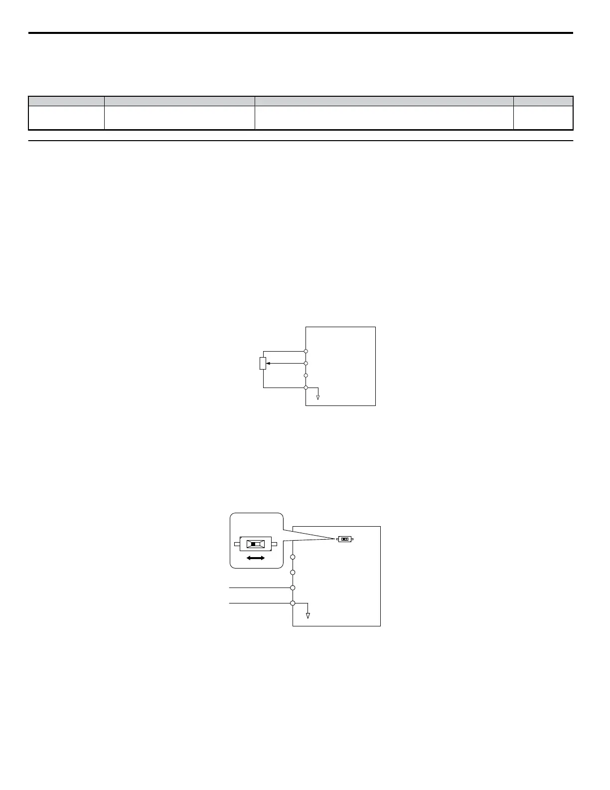
Control Circuit Terminal A2 (Voltage/Current Input):
Use control circuit Terminal A2 when supplying the frequency reference with a current signal between 4 to 20 mA. Use the following switch and parameter
settings to configure Terminal A2 for 0 to 20 mA or 4 to 20 mA input.
• Set the signal level for analog input A2 to current input (H3-09 = “2” for 4 to 20 mA, H3-09 = “3” for 0 to 20 mA).
• Set the function for analog input A2 to frequency reference (H3-10 = “0”) to command terminal A2 to be a frequency reference.
• Set DIP switch S1 to the I position for a current signal input.
Drive
A1
A2
Main Frequency Reference
(voltage input)
Main Frequency Reference
(current input)
AC
Frequency Reference
Common
+ V (+10.5 V, 20 mA)
(0) 4 - 20 mA input
DIP switch S1
V I
Figure 4.13 Current Input for the Main Frequency Reference
Switching between Main/Auxiliary Frequency References
To configure the frequency reference to switch between analog input A1 and A2 (main/aux frequency switch), use the following setup:
1.
Set the frequency reference source to terminals (b1-01 = “1”).
2.
Set one of the digital inputs to auxiliary reference 1, H1-oo = “3” (preset for terminal S5).
3.
Set input signal type of terminal A2 using dip switch S1 and parameter H3-09.
4.
Set the function of analog input A2 to Auxiliary frequency (H3-10 = “3”).
4.6 Basic Drive Setup Adjustments
76
YASKAWA ELECTRIC SIEP C710606 18A YASKAWA AC Drive – V1000 Technical Manual (Preliminary)

 Loading...


